New version is Still todo
also check https://bmcu.wanzii.cn/doc/build/370hall.html
¶ Introduction
This guide is written for BMCU-C v0.2 channel component assembly.
¶ Pre-assembly Preparation
Integration package for this tutorial: Coming soon, please check group files
- A fully soldered BMCU
Hall versioncircuit board: ensuring no soldering defects (cold joints, missing solder, bridges, wrong components, etc.). - Flash the mainboard with Hall version compatible firmware. As of 21/07/25, the latest available firmware is
v0020 - 3D printed housing : You can choose between
1. The original file from the author
2. BMCU-C improved version by @Kongmingn
3. BMCU-C improved version by @ZhuBuZaiHu (Highly recommended!!!)
I strongly recommend you to use the 3rd link! - Print this tool to check the polarity of magnets later Magnet Polarity Detector
¶ Main Content
¶ Component Names
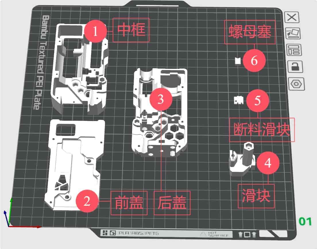
- Middle Frame
- Front Cover
- Bottom Frame
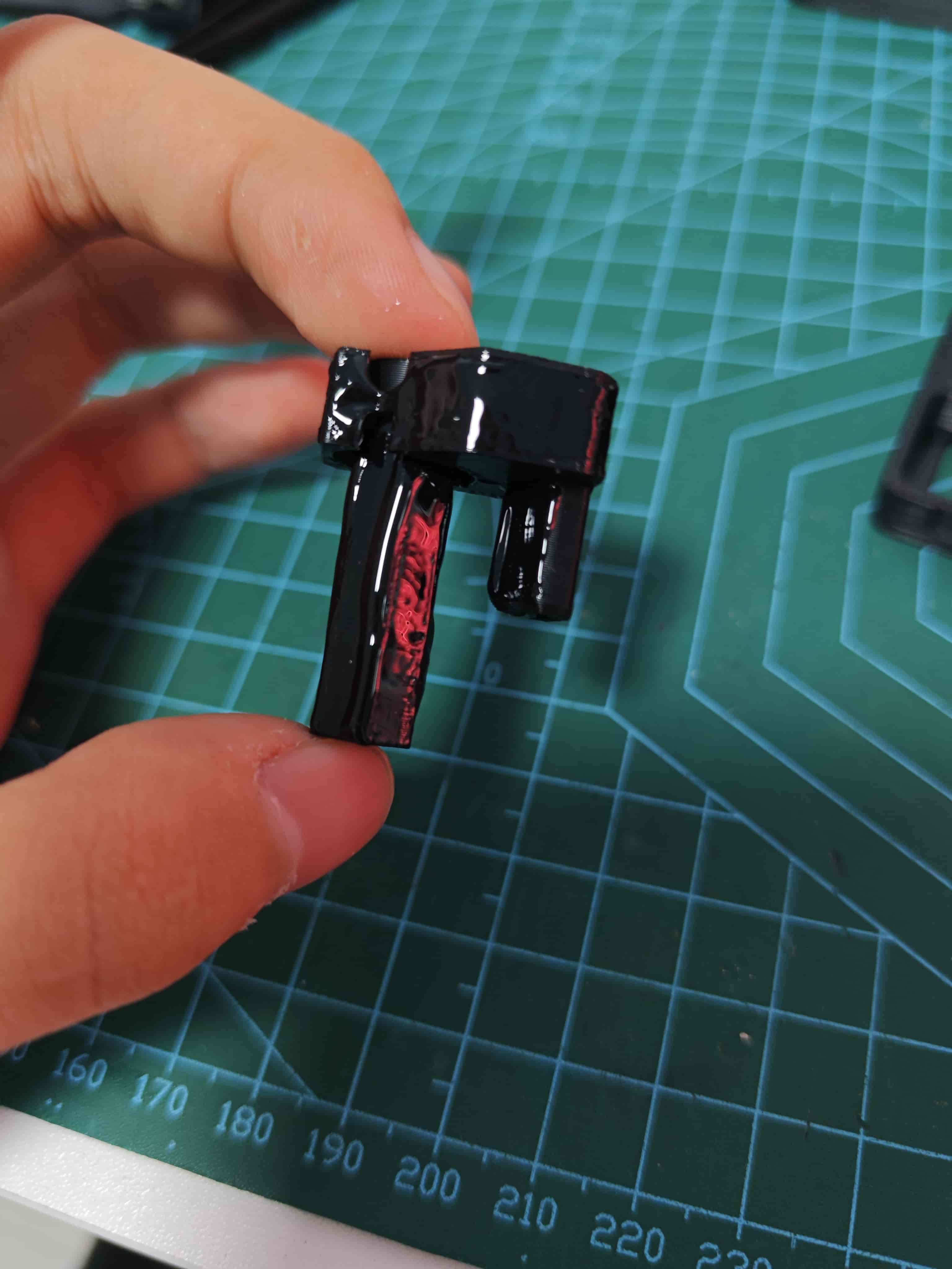
- Buffer Slider
- Filament Detection Slider
- Nut Plug
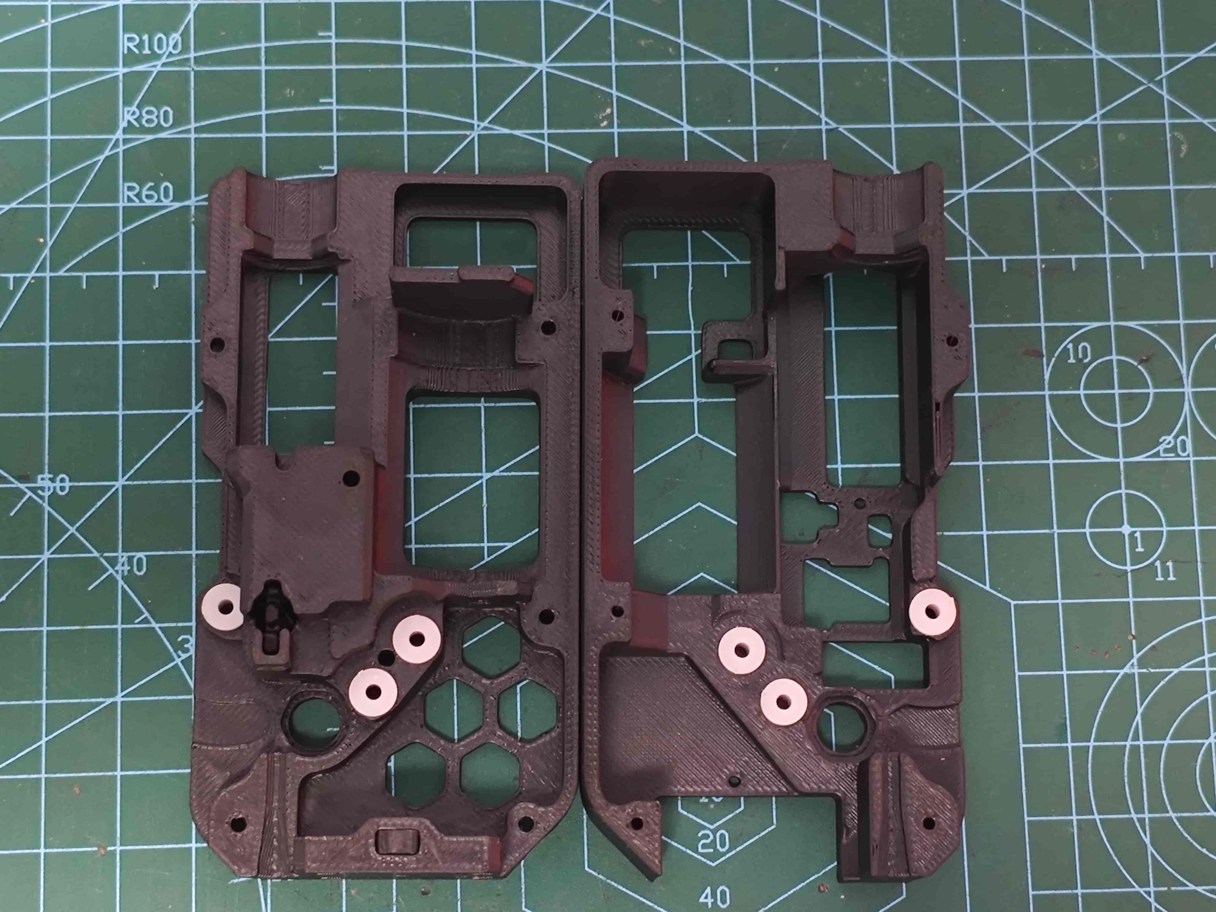
¶ Install Bushing
Insert 62B bushing into back cover and middle frame as shown
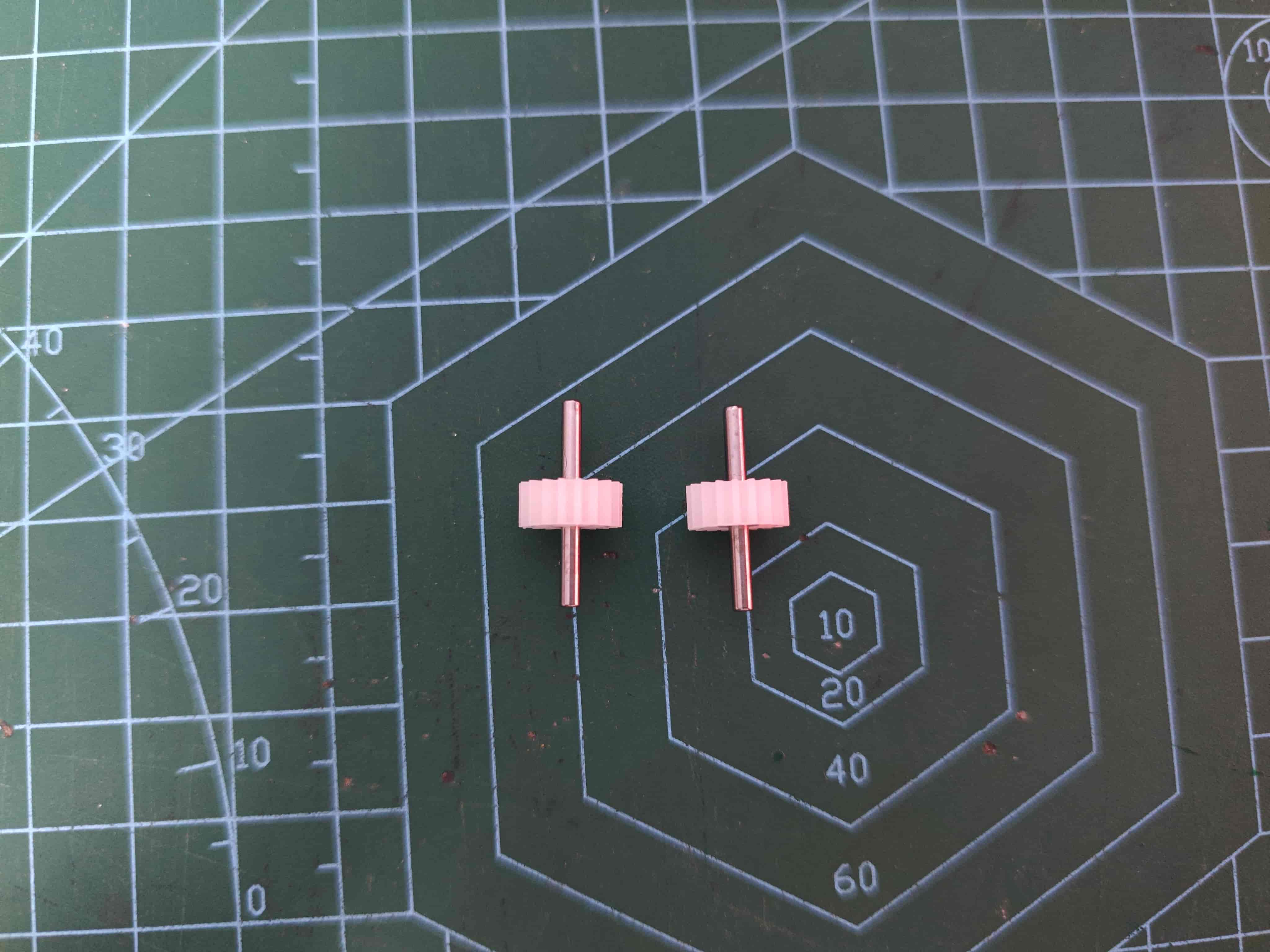
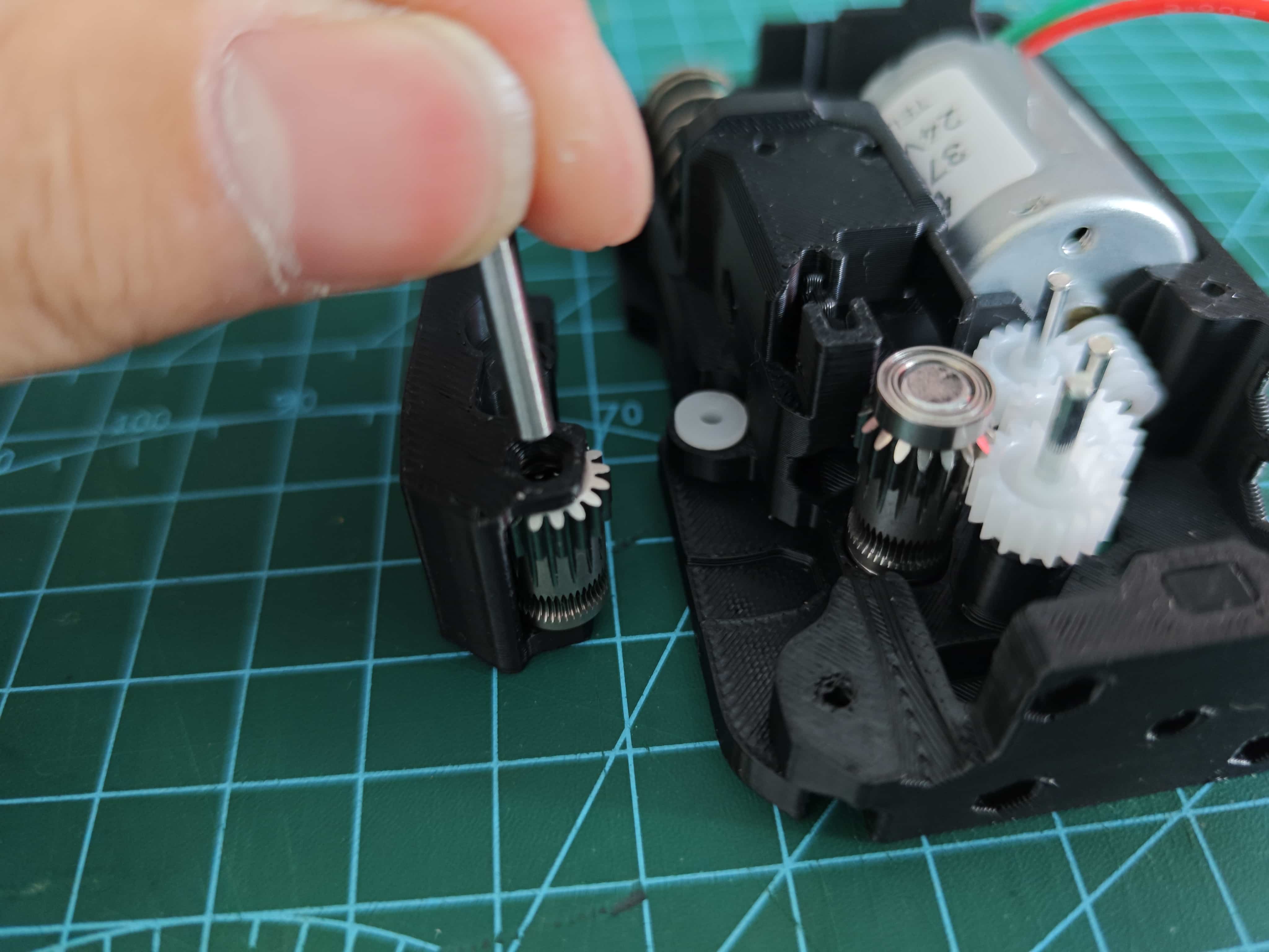
¶ Assemble D2*20 Shaft with 182A Gear
Ensure both ends protrude approximately equal lengths
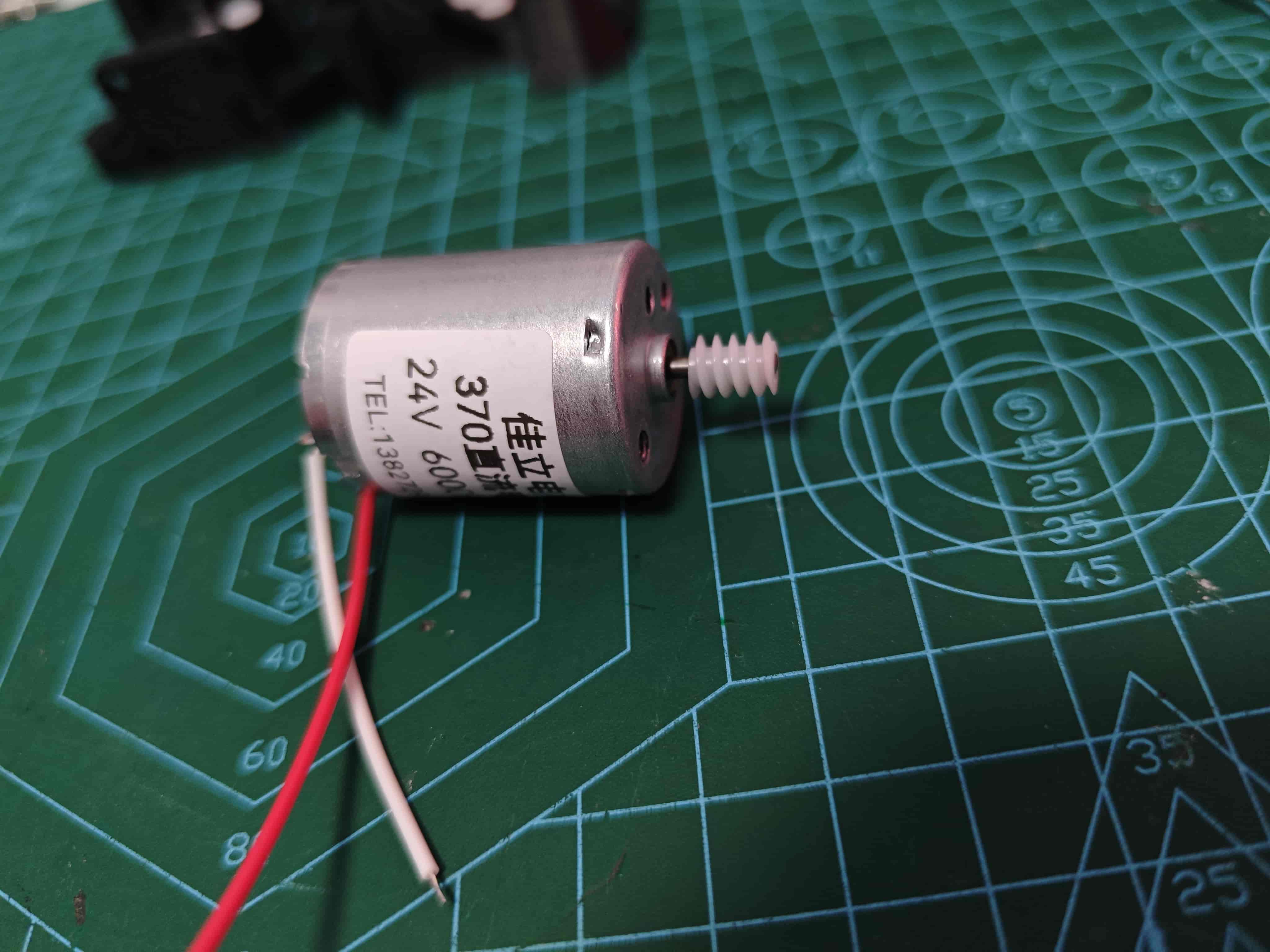
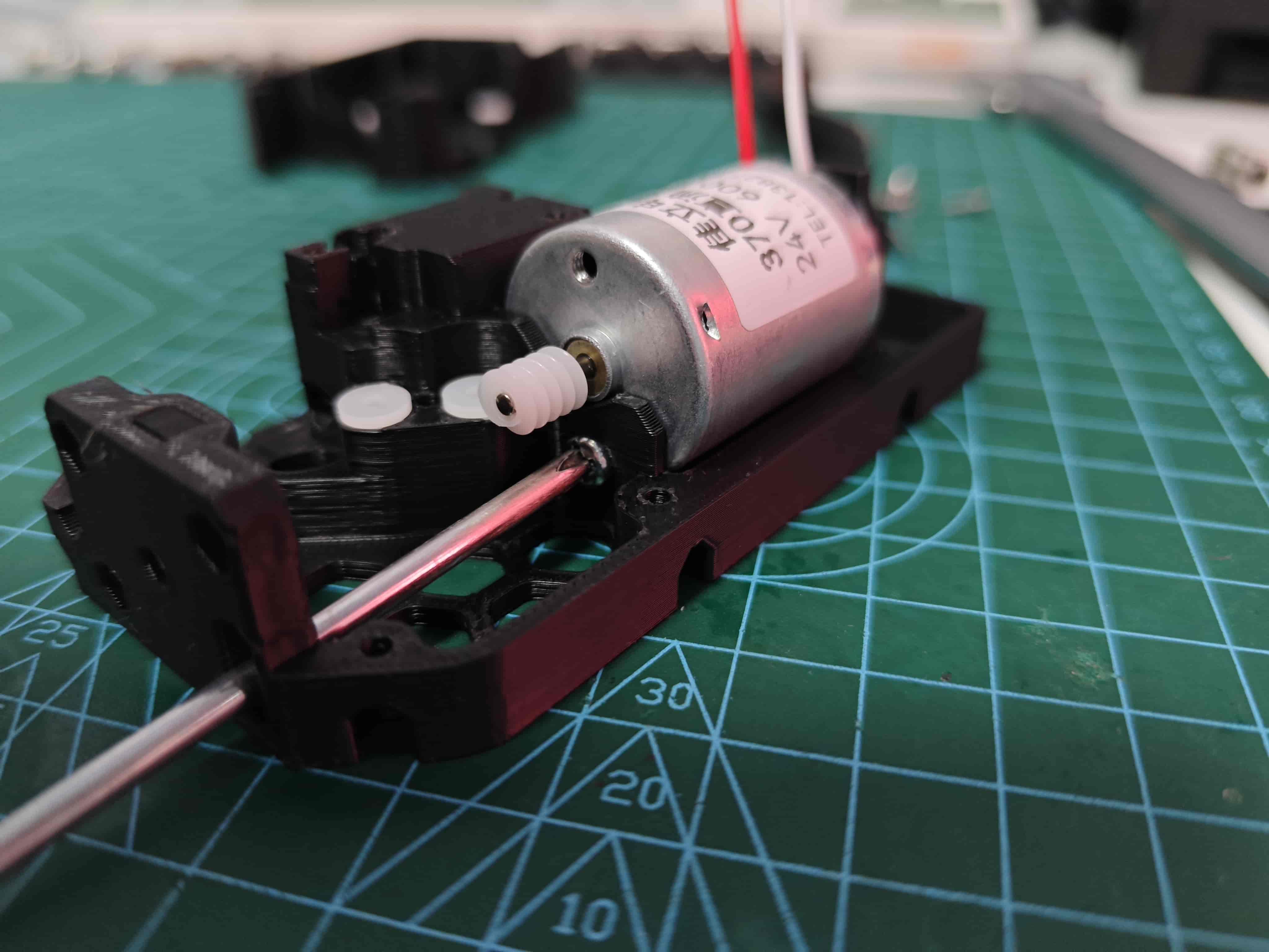
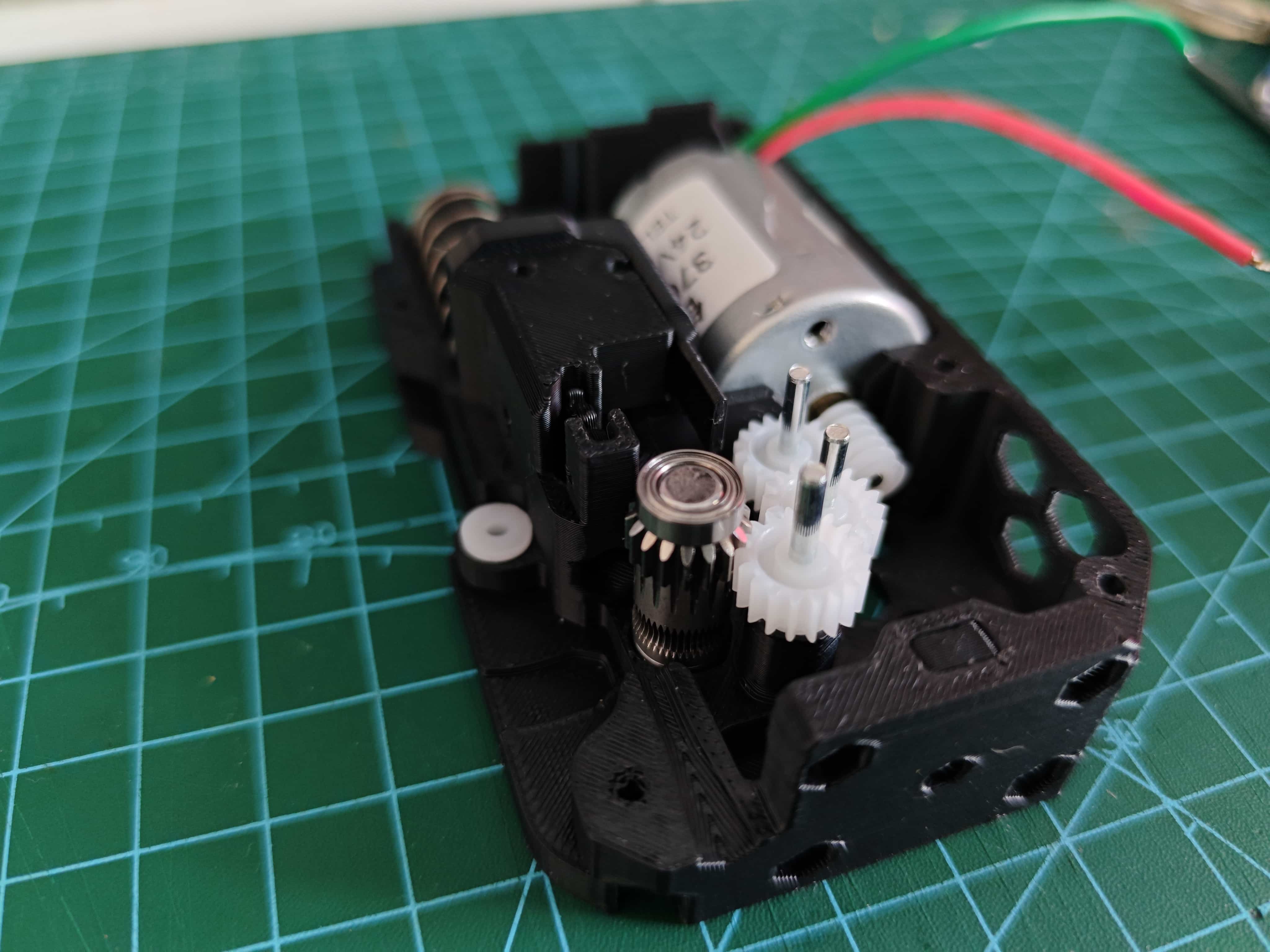
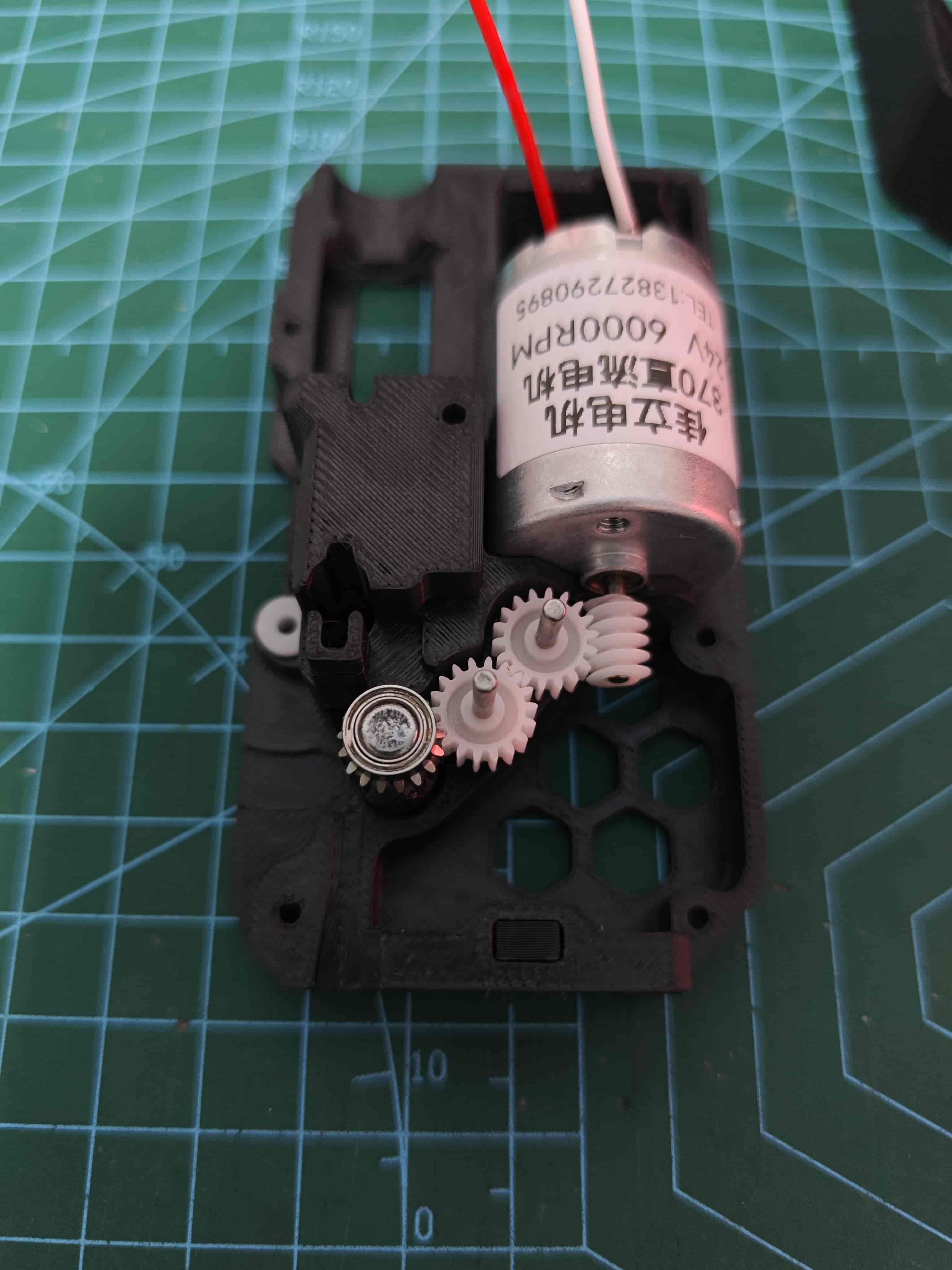
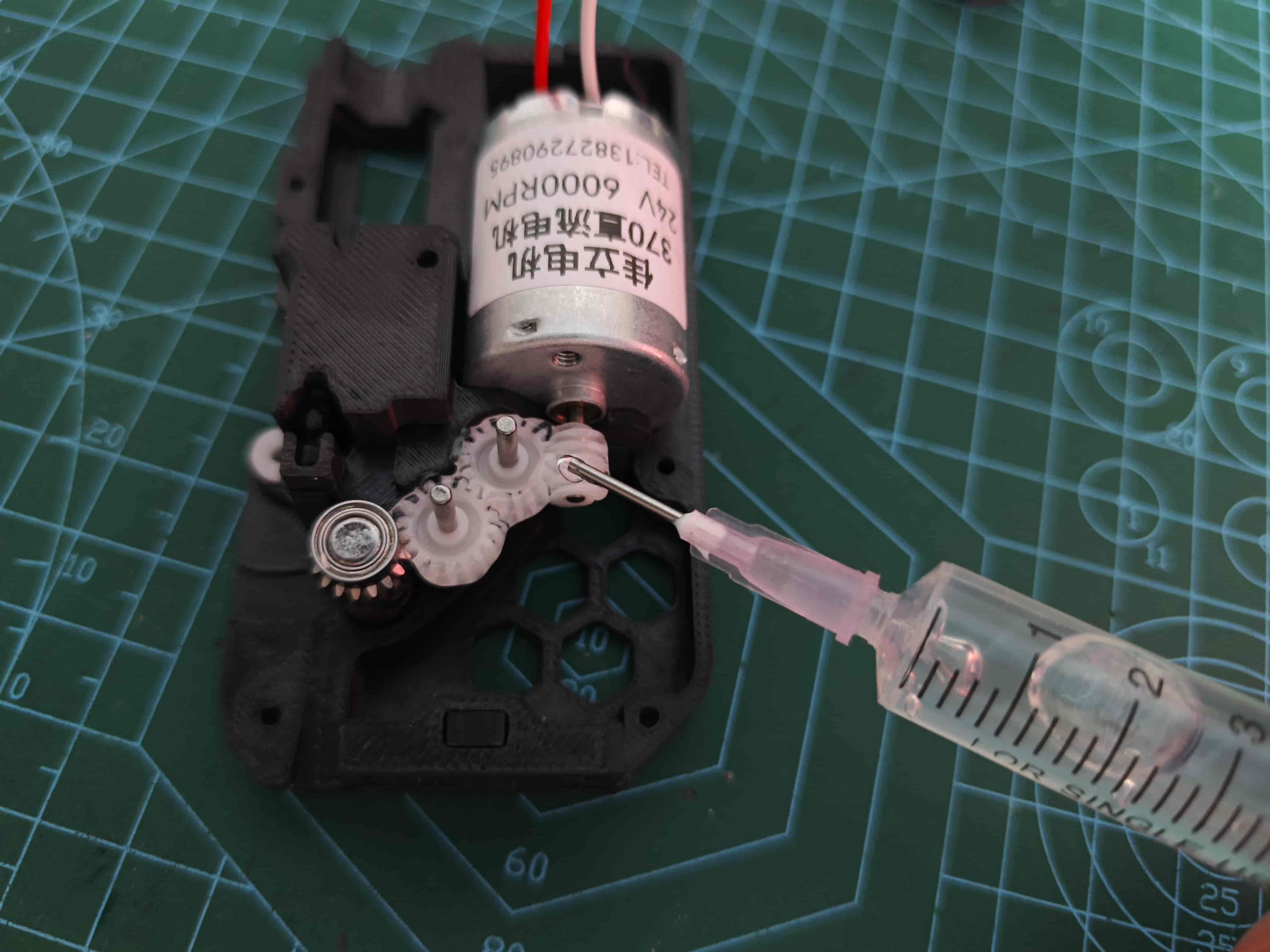
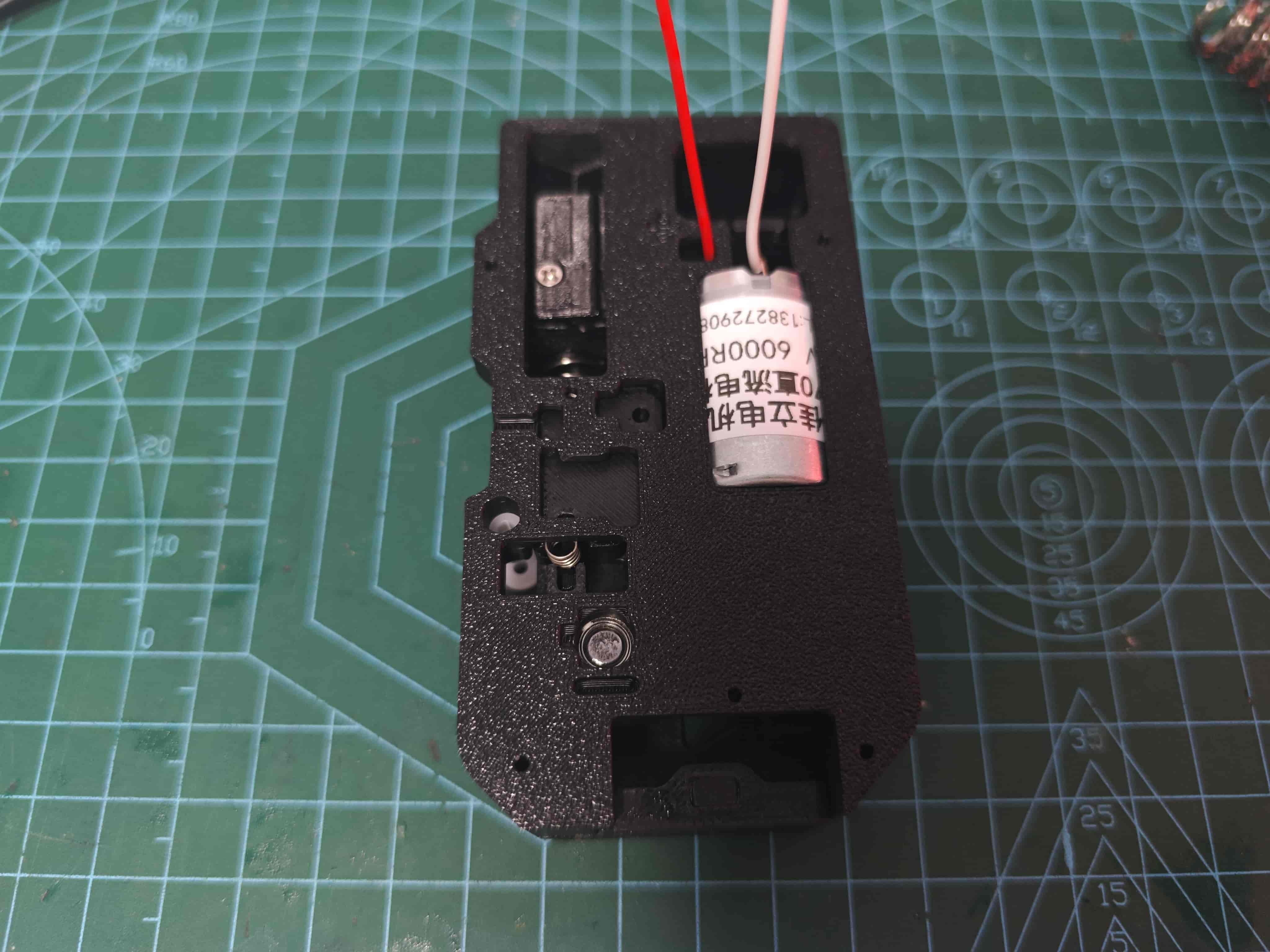
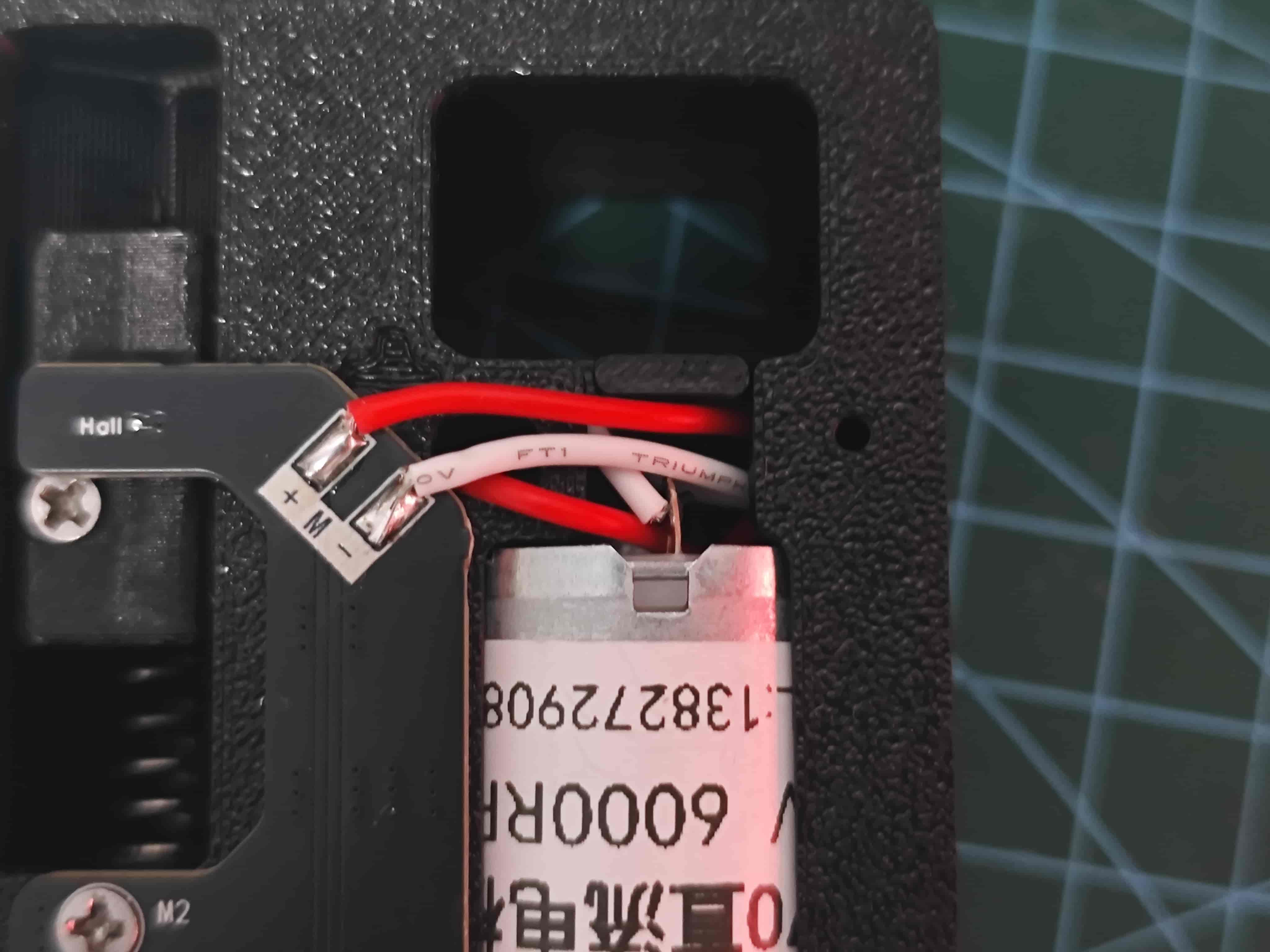
¶ Install Worm Gear on 370 Motor and Solder Wires
Align motor shaft with worm gear. Apply 502 glue if needed.
The pin with red dot is positive
¶ Determine Slider Magnet Polarity
You can use the magnetic pole detection device designed by @Wanzi to detect the magnetic poles of a magnet.
Magnet Polarity Detector - Link Makerworld
Find a container and add water
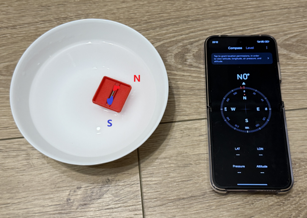
Attach two D3*10 magnets or one single D3*20 magnets, place in the Magnet Polarity Detector, and float on water
The geographic north pole is slightly different from the geomagnetic north pole, so just take the one with a similar direction.
Once stable, the end pointing south is the south pole, the other end is north pole
¶ Install Magnet in Slider
With slider oriented as shown, insert magnet (south pole near pneumatic)
Important: Center the magnet in the slider's magnet mounting position
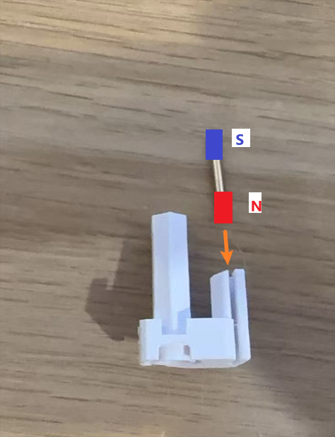
Emergency withdrawal of the picture, previously shown with the wrong magnetic poles!
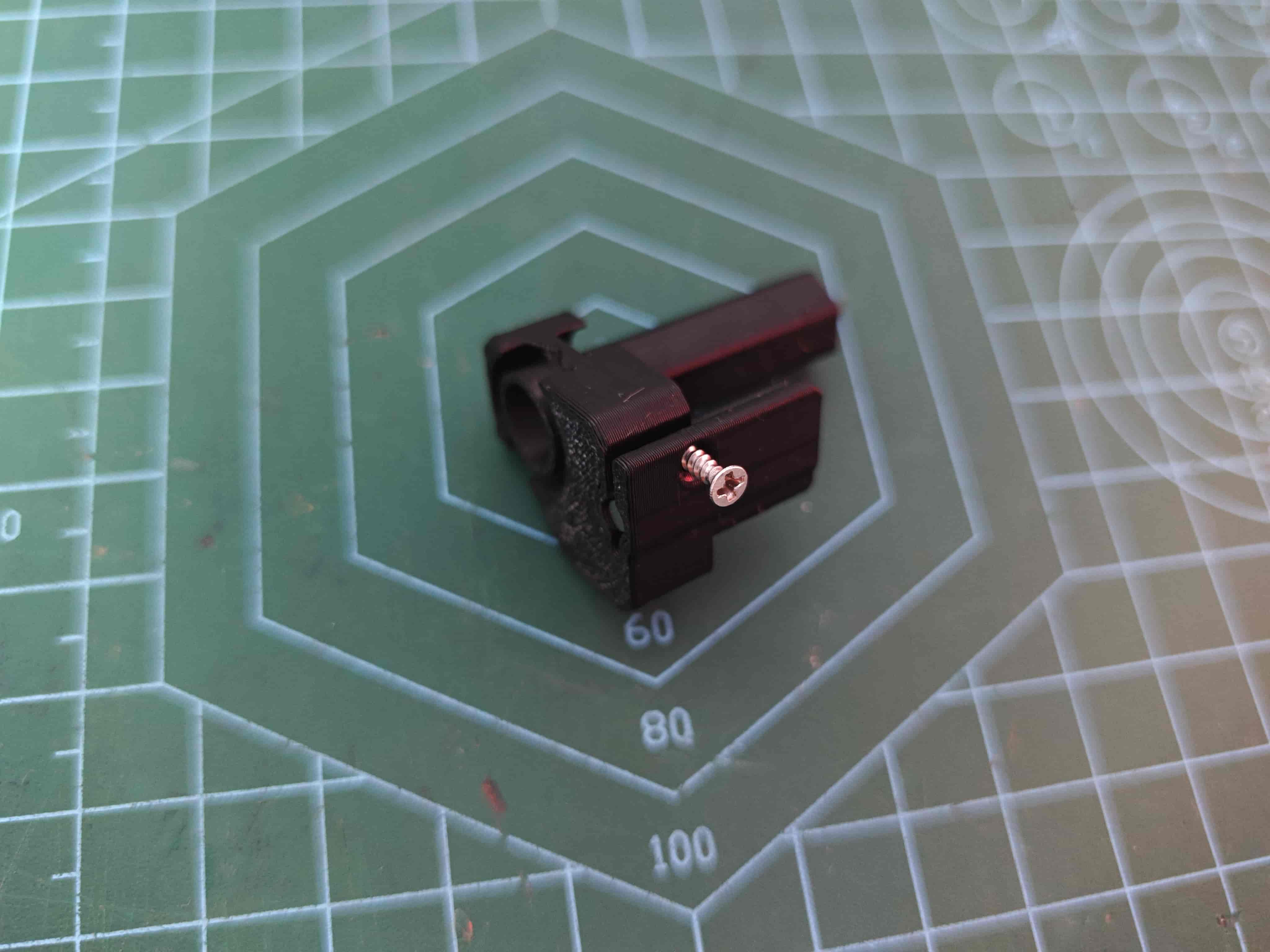
¶ Secure Slider Magnet
Use M2*8 self-tapping screw to secure
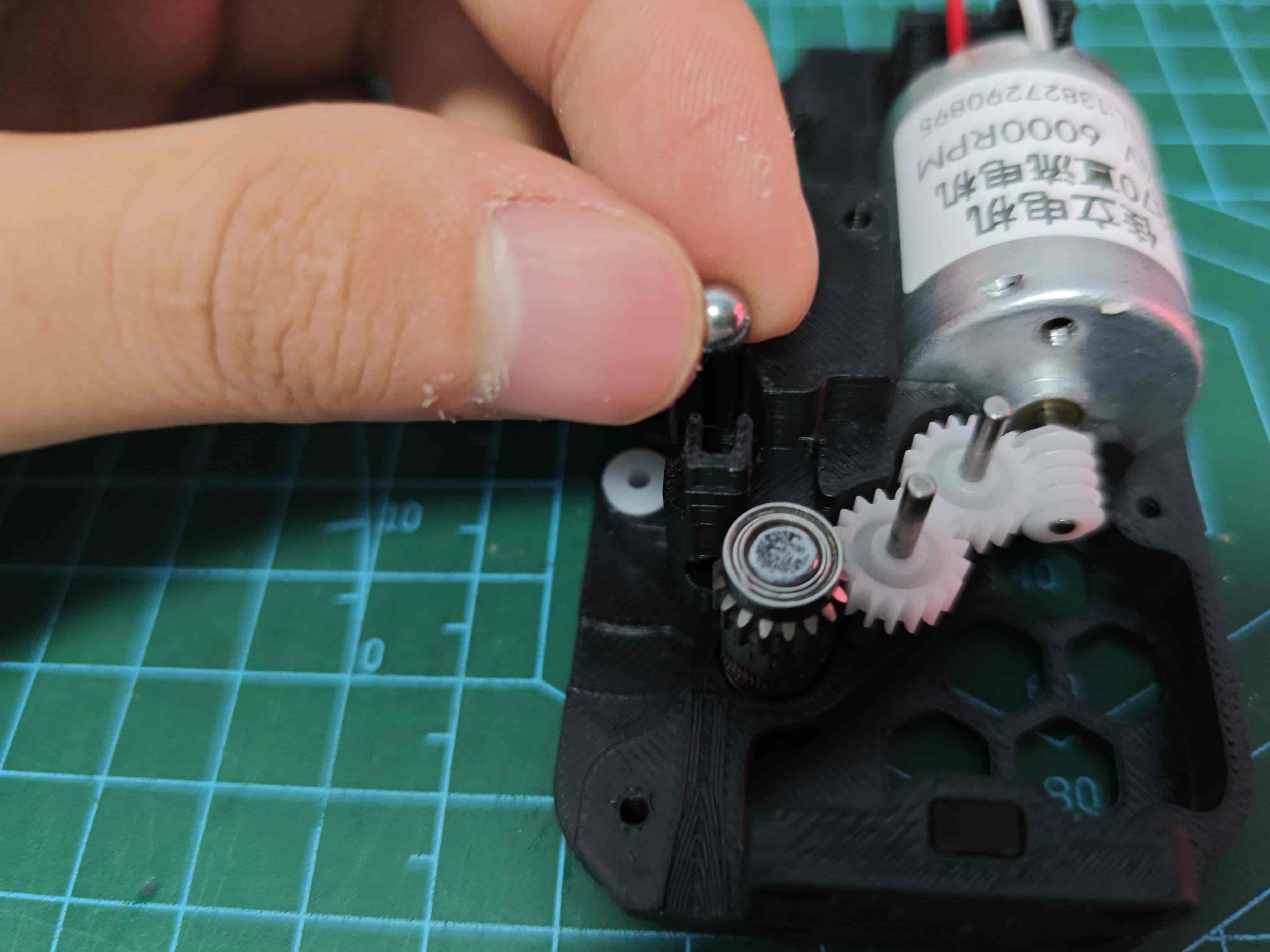
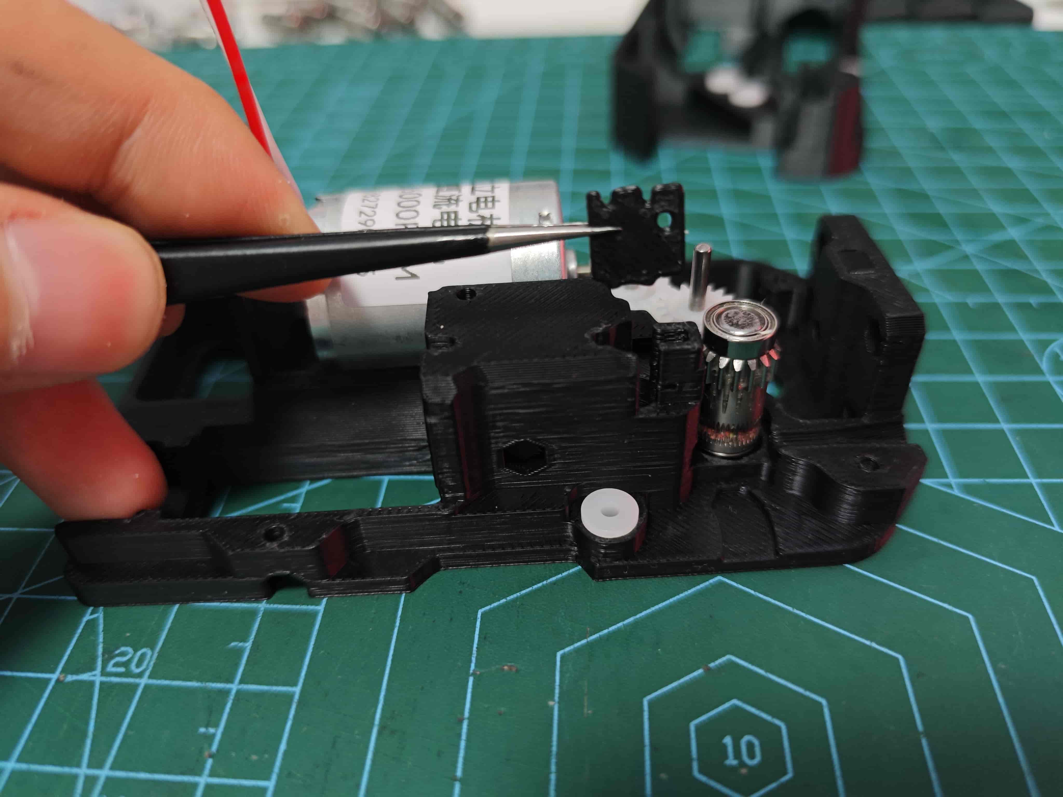
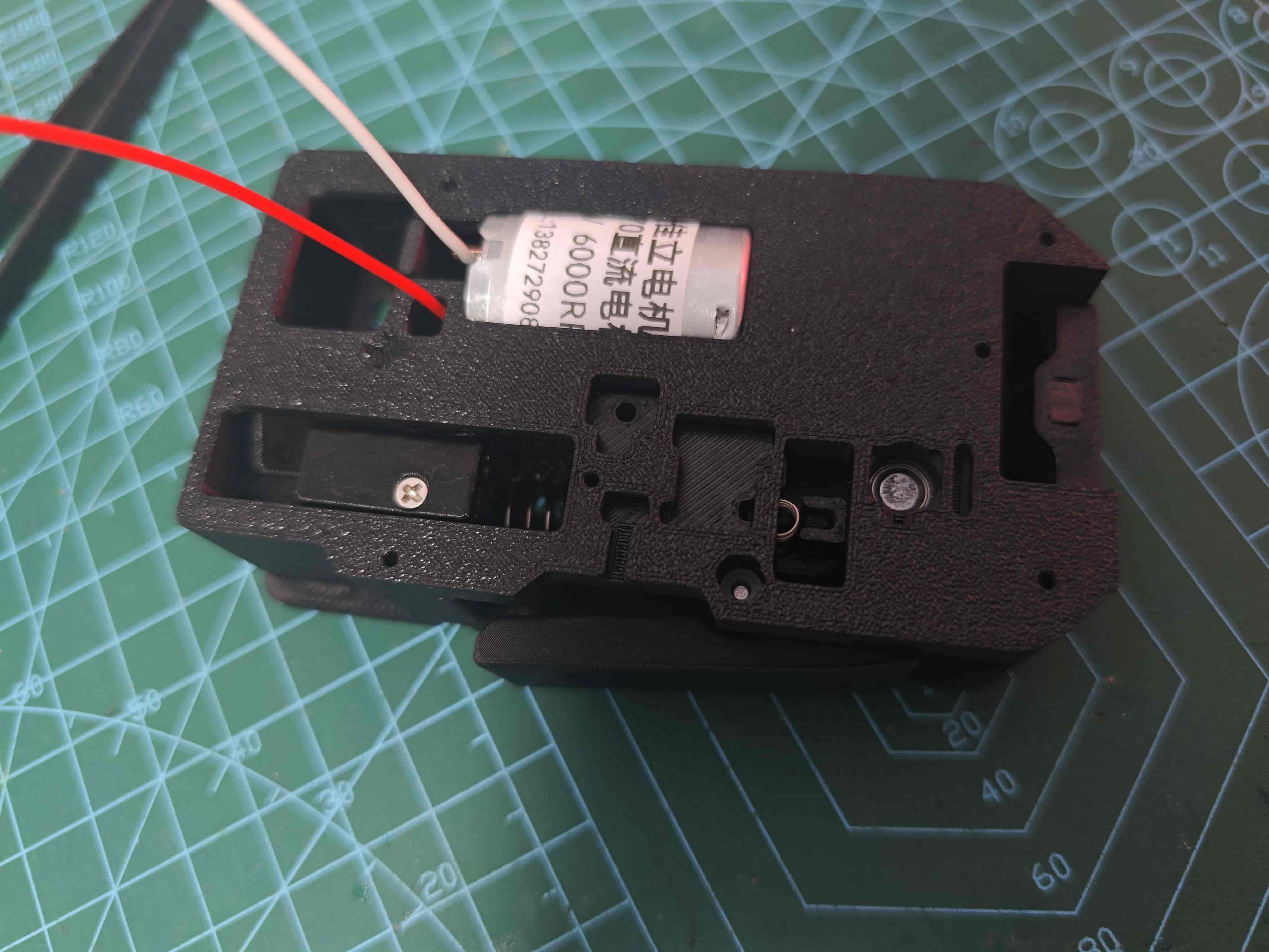
¶ Install Motor
Place motor in position and secure with M3*5 machine screw
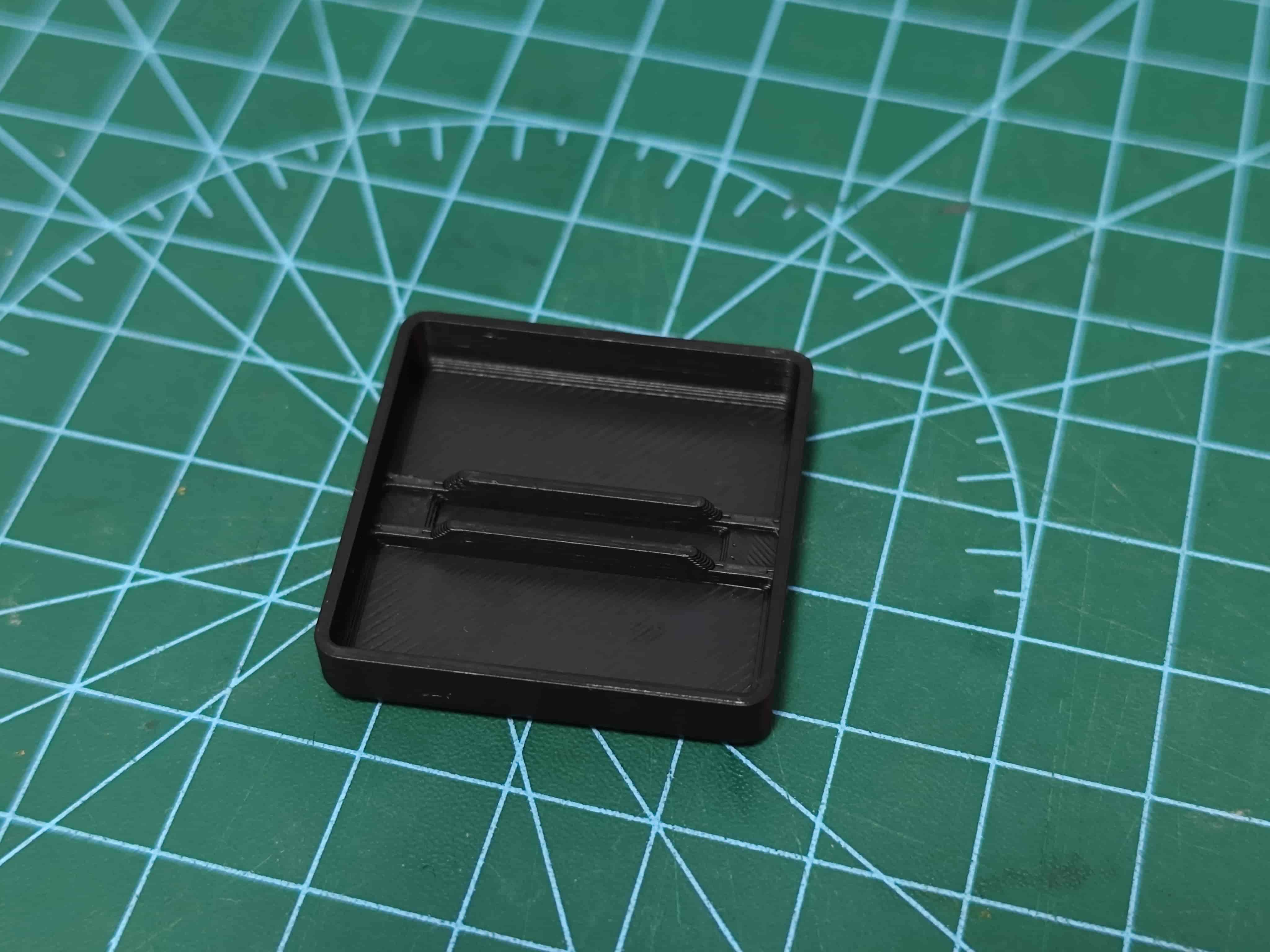
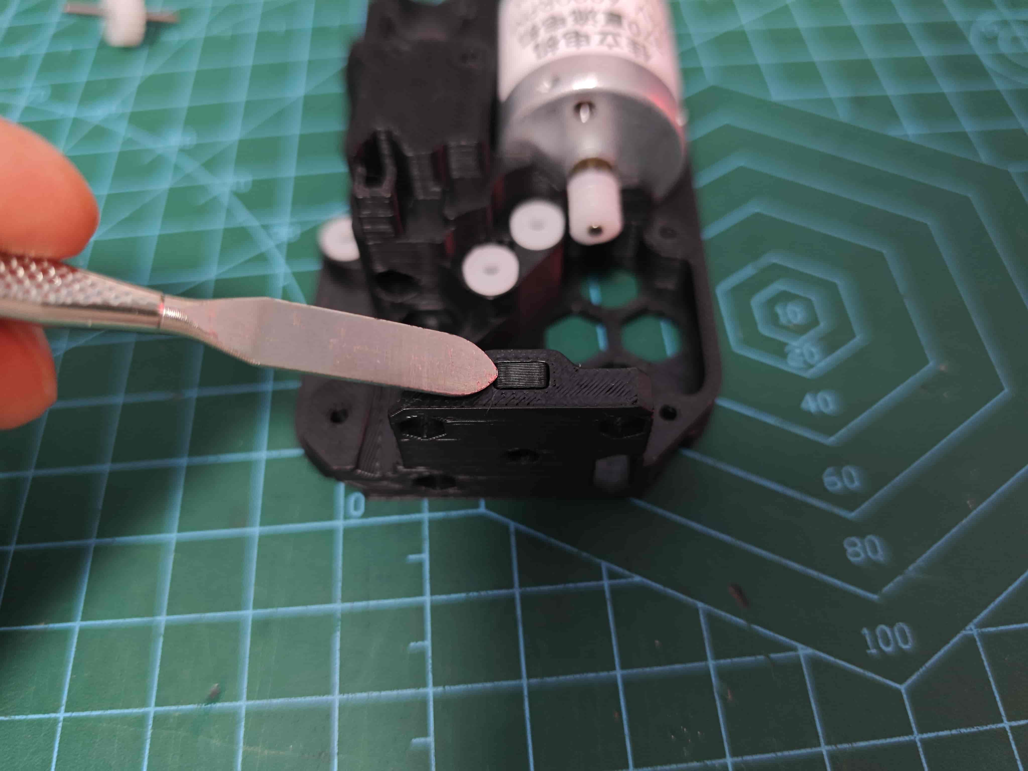
¶ Install Nut and Nut Plug
Place M3 hex nut in recess and insert nut plug to secure
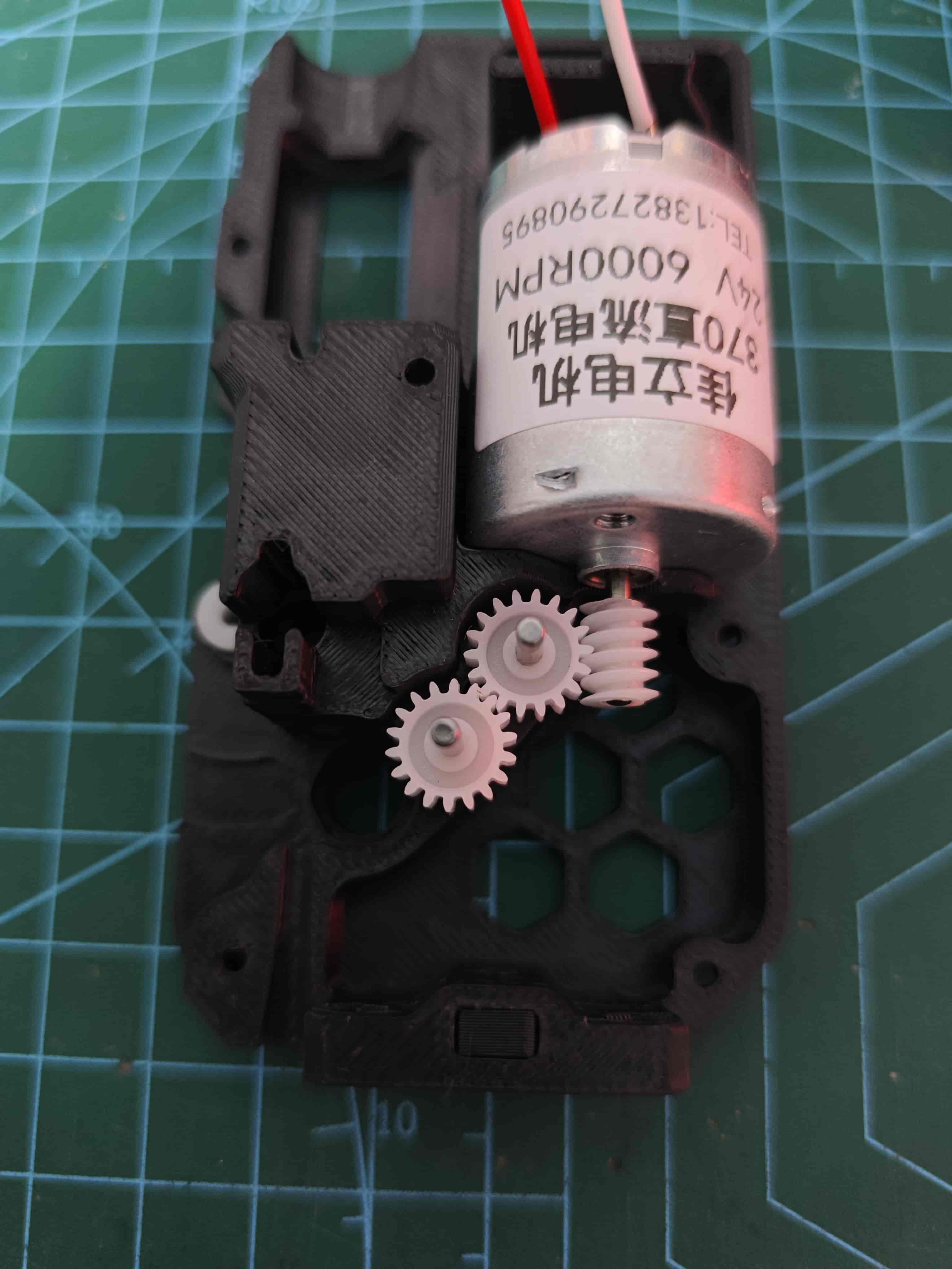
¶ Install Gear
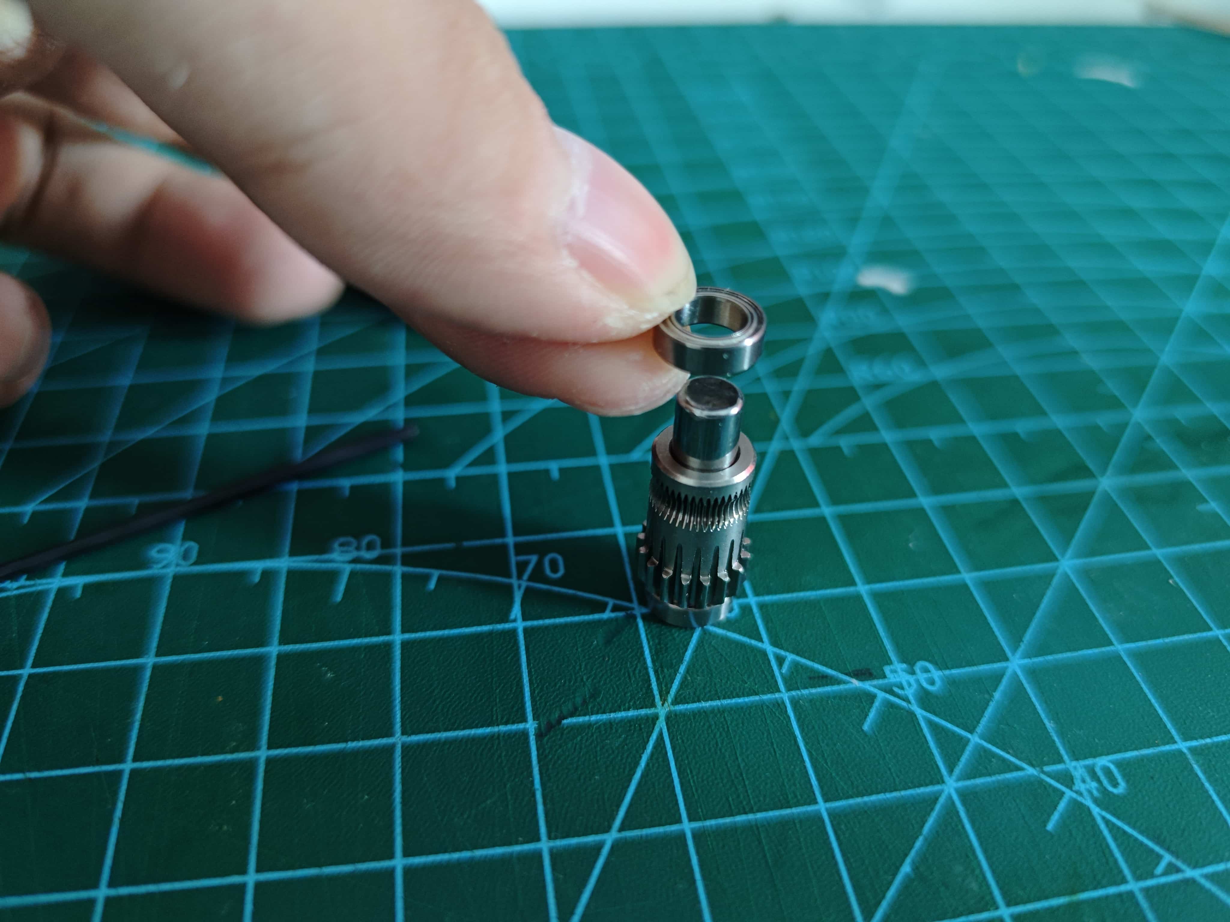
¶ Assemble BMG Drive Wheel
These are all the parts included in the BMG gear set:
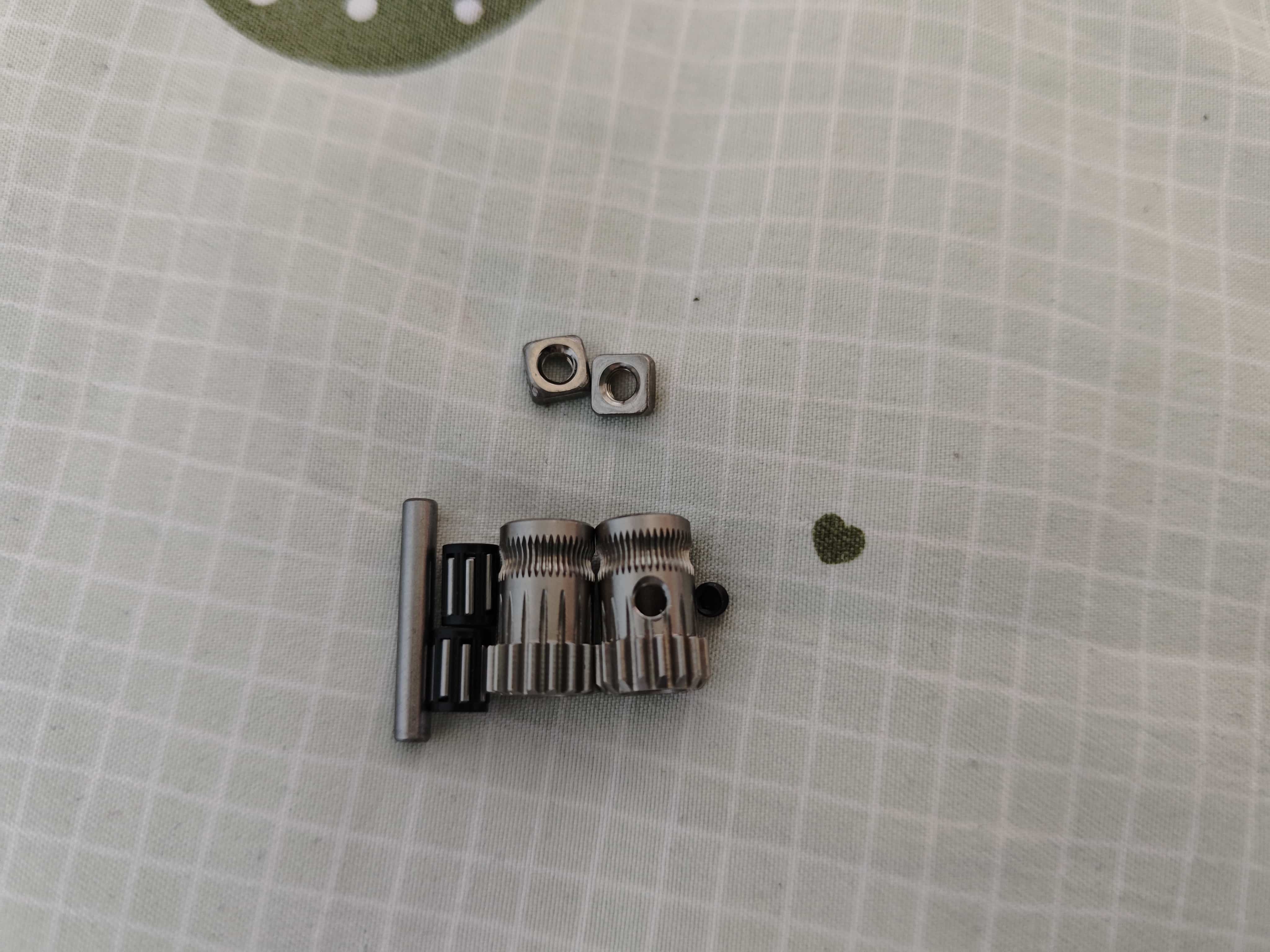
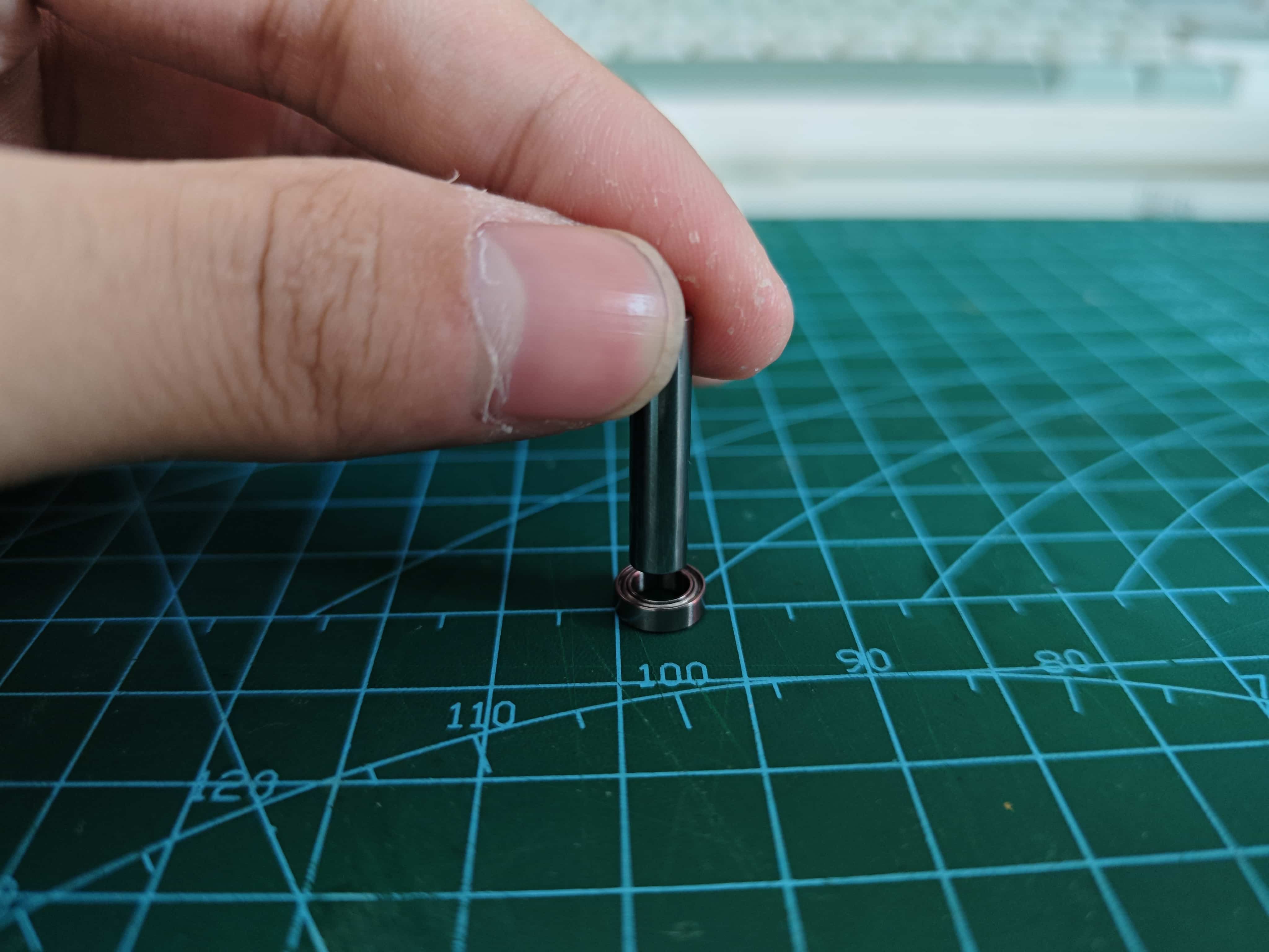
Take one D5x22mm shaft and two MR85ZZ bearings. Press the shaft into one bearing until flush.
Apply even force during installation. Install the shaft vertically to avoid damaging the bearing. Check shaft precision before use—some may not be perfect.
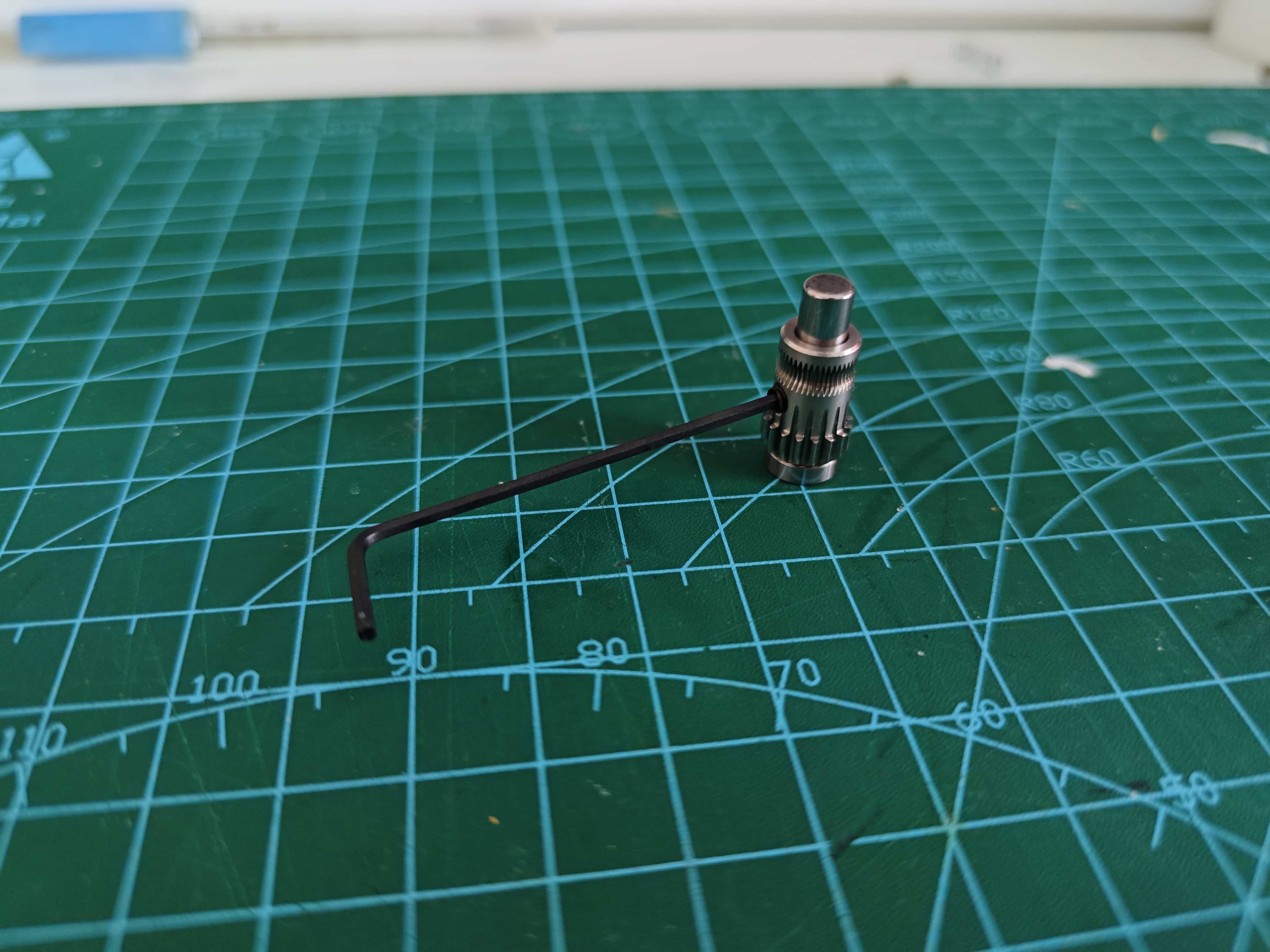
Place the BMG gear with set screw hole as shown:
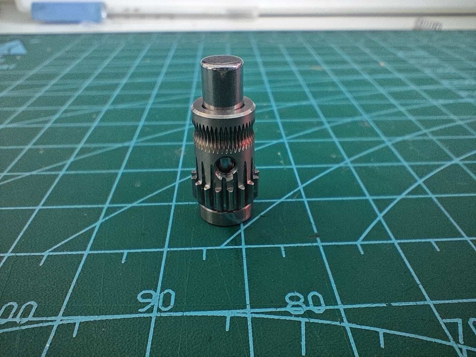
Insert the set screw using a hex key.
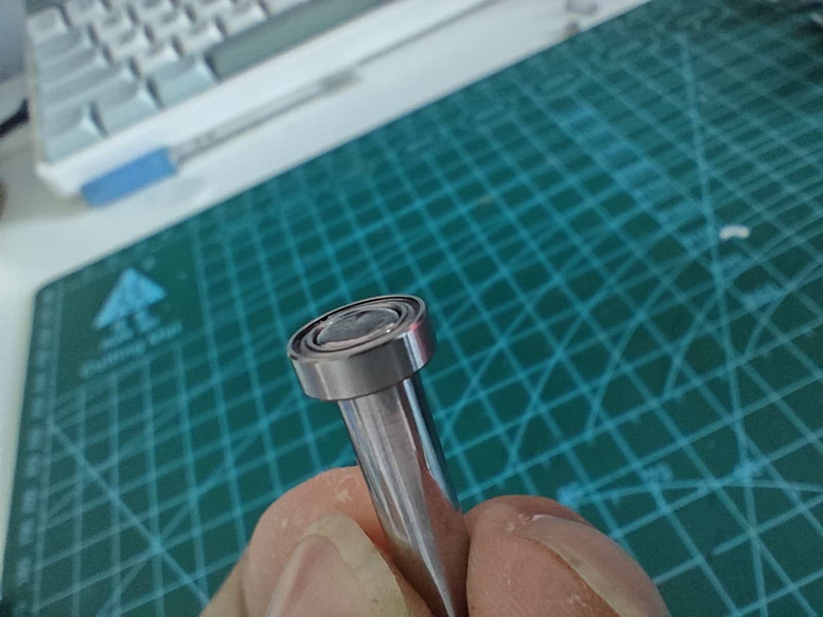
Install the top bearing, ensuring it sits flush against the gear.
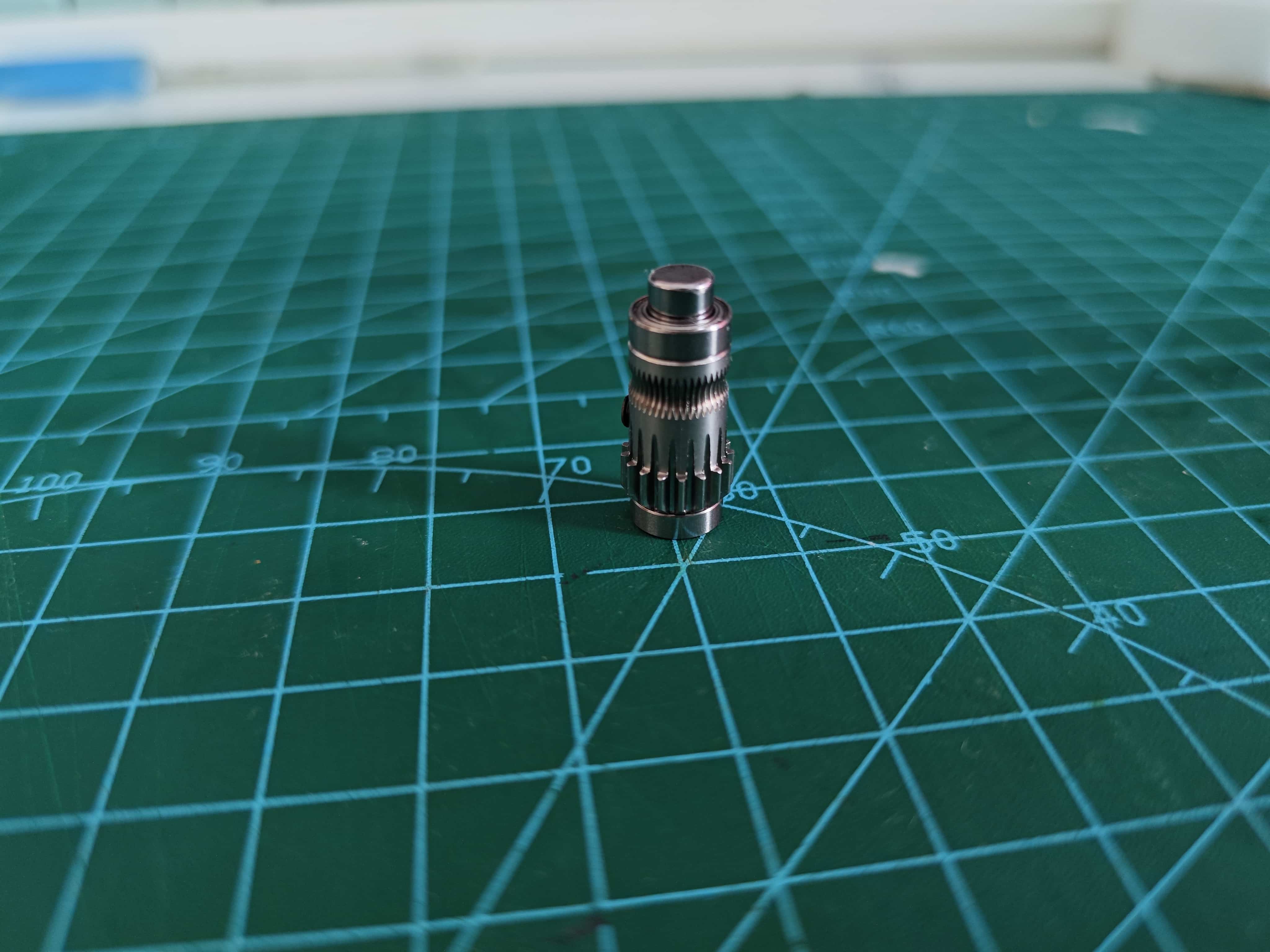
Place the assembled BMG drive gear into the back frame, gear facing upward.
¶ Assemble BMG Driven Wheel
Insert two needle bearings into the Driven gear (no set screw hole).
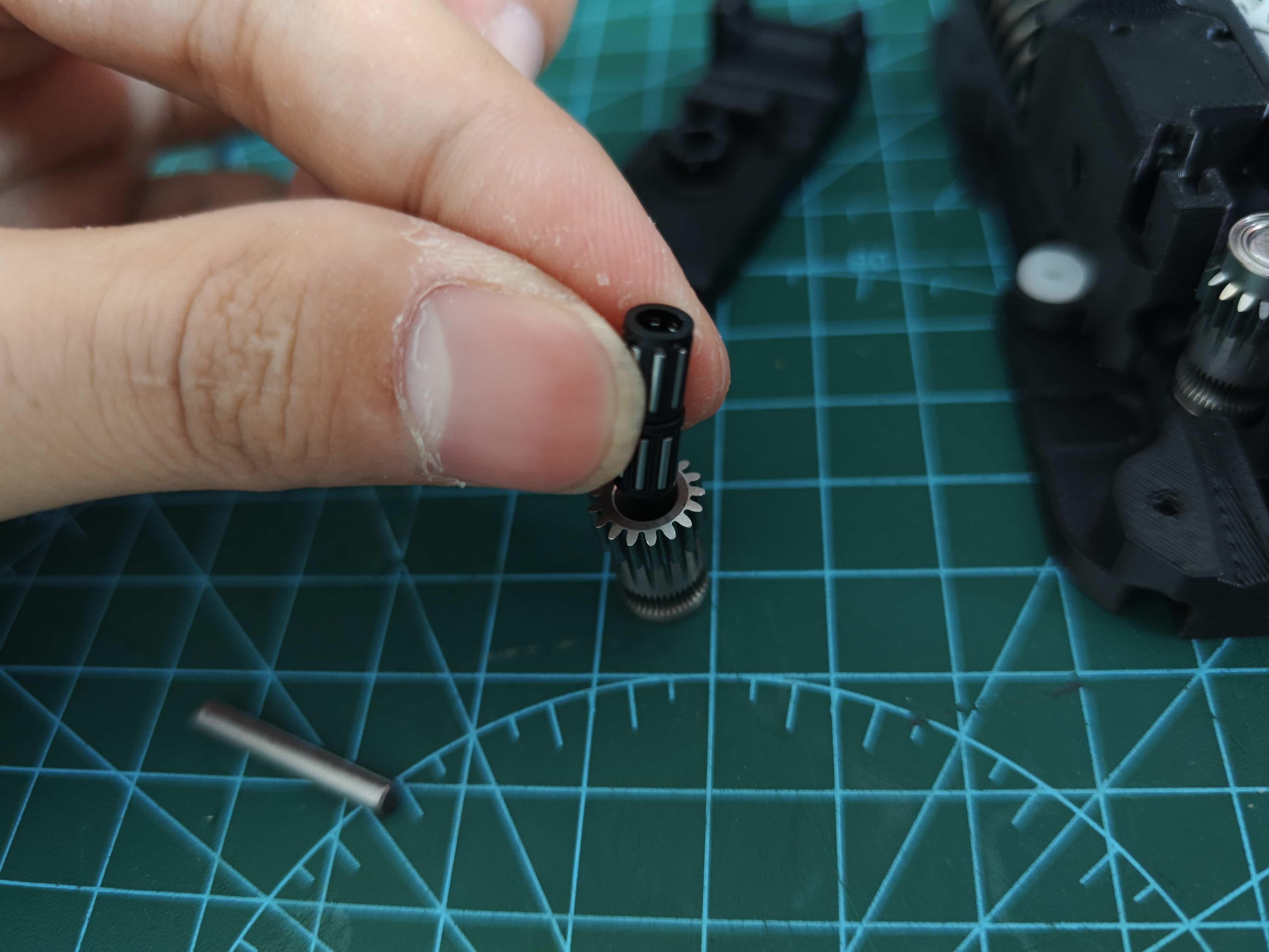
Place it into the lever, making sure the direction is correct, and insert the shaft from the BMG kit.
¶ Install BMG Drive Wheel
¶ Install Ball Bearings
¶ Install Filament Break Slider
Note slider orientation
¶ Apply Grease
Here @Wanzi uses lubricant, but please note that we do not recommend the use of lubricant, but rather a grease with a certain viscosity, such as the one supplied with the Bambulab machine.
But also, you should not choose a grease with too high a viscosity, for example, it is not recommended to use a grease for bicycles.
Lubricate gears (can remove to apply and reinstall, BMG doesn't need lubrication)
Lubricate slider (optional)
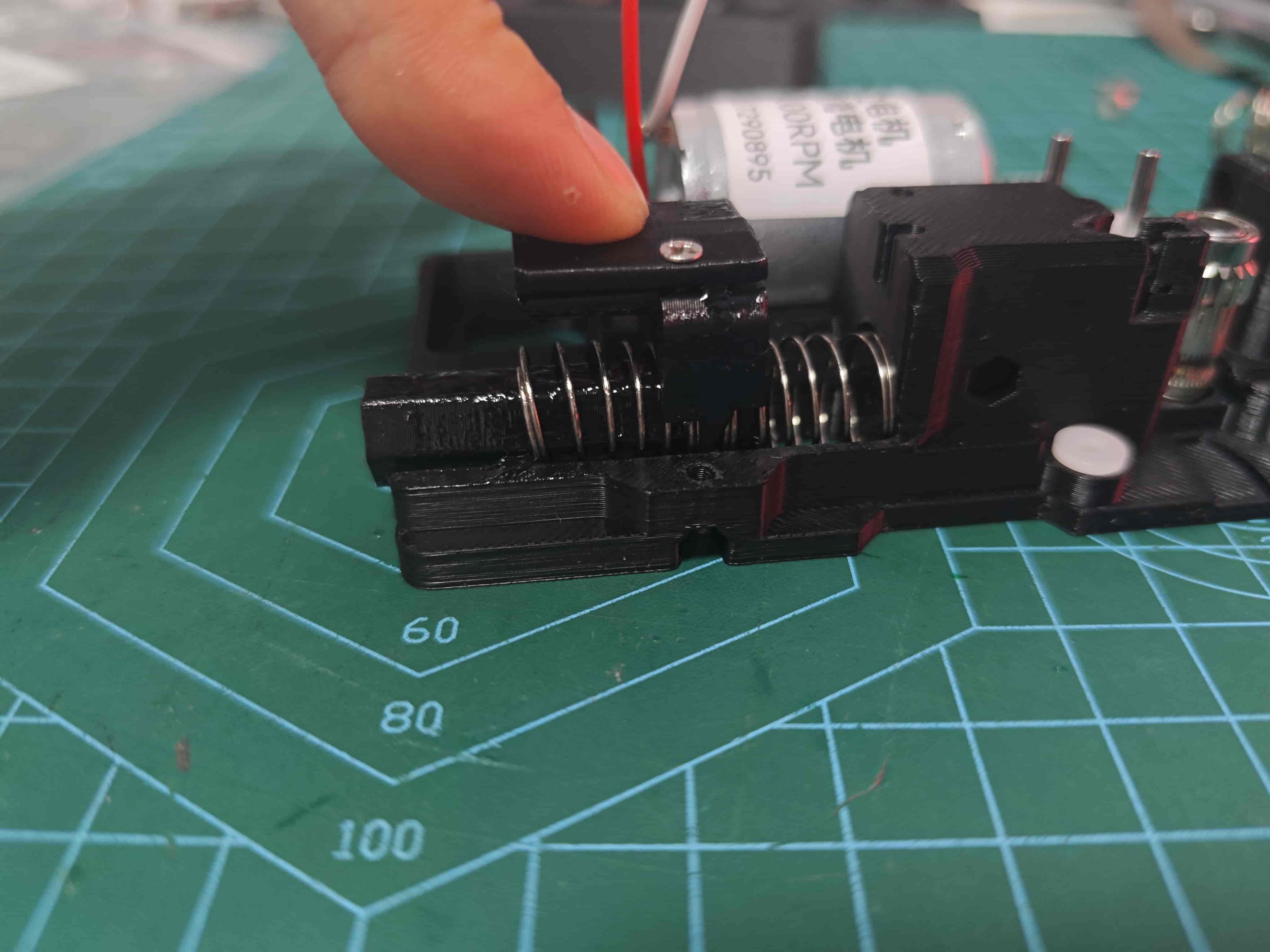
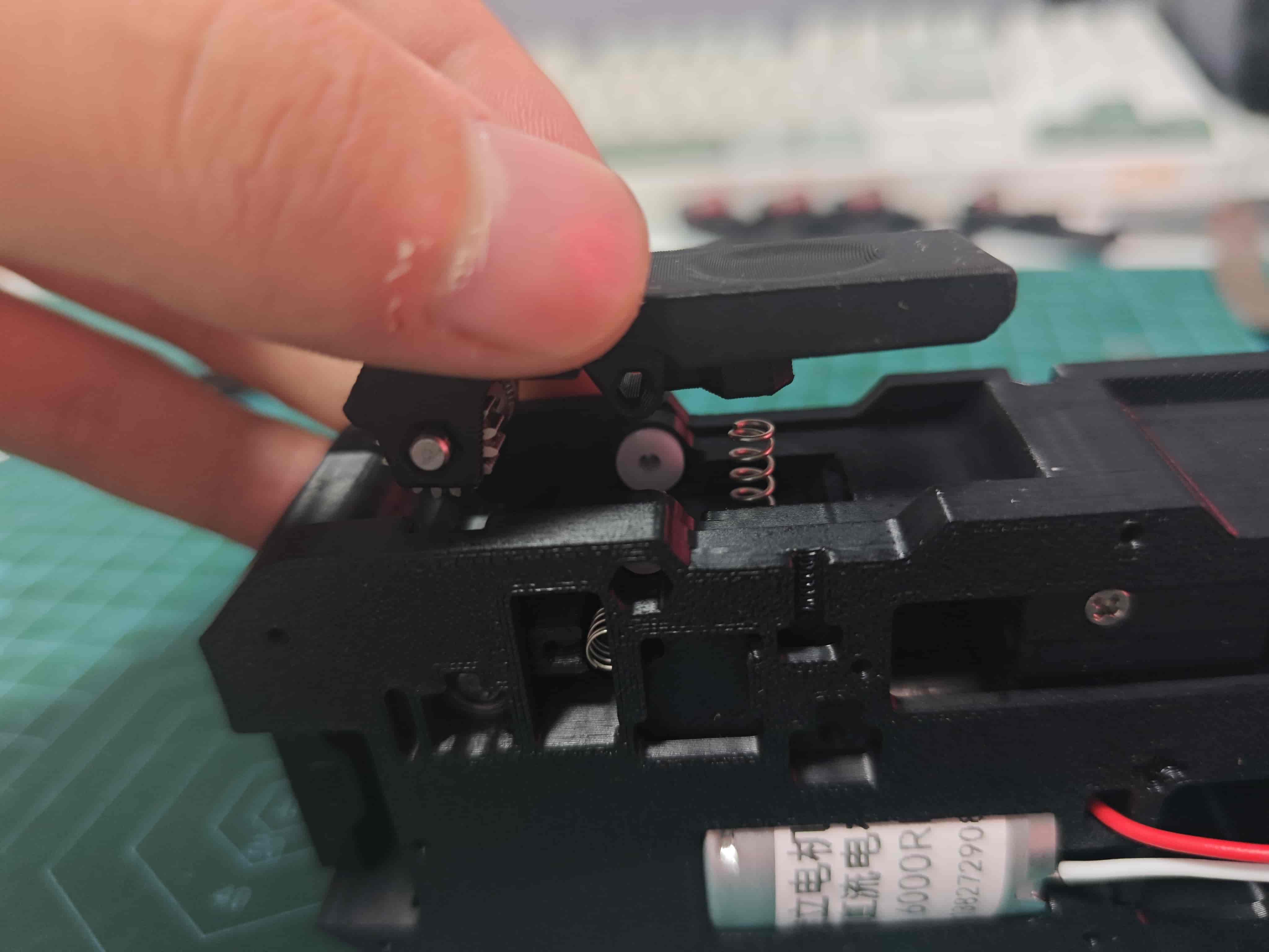
¶ Install Slider and Springs
Place two 0.8*12*25 springs at slider ends, secured in mounting positions
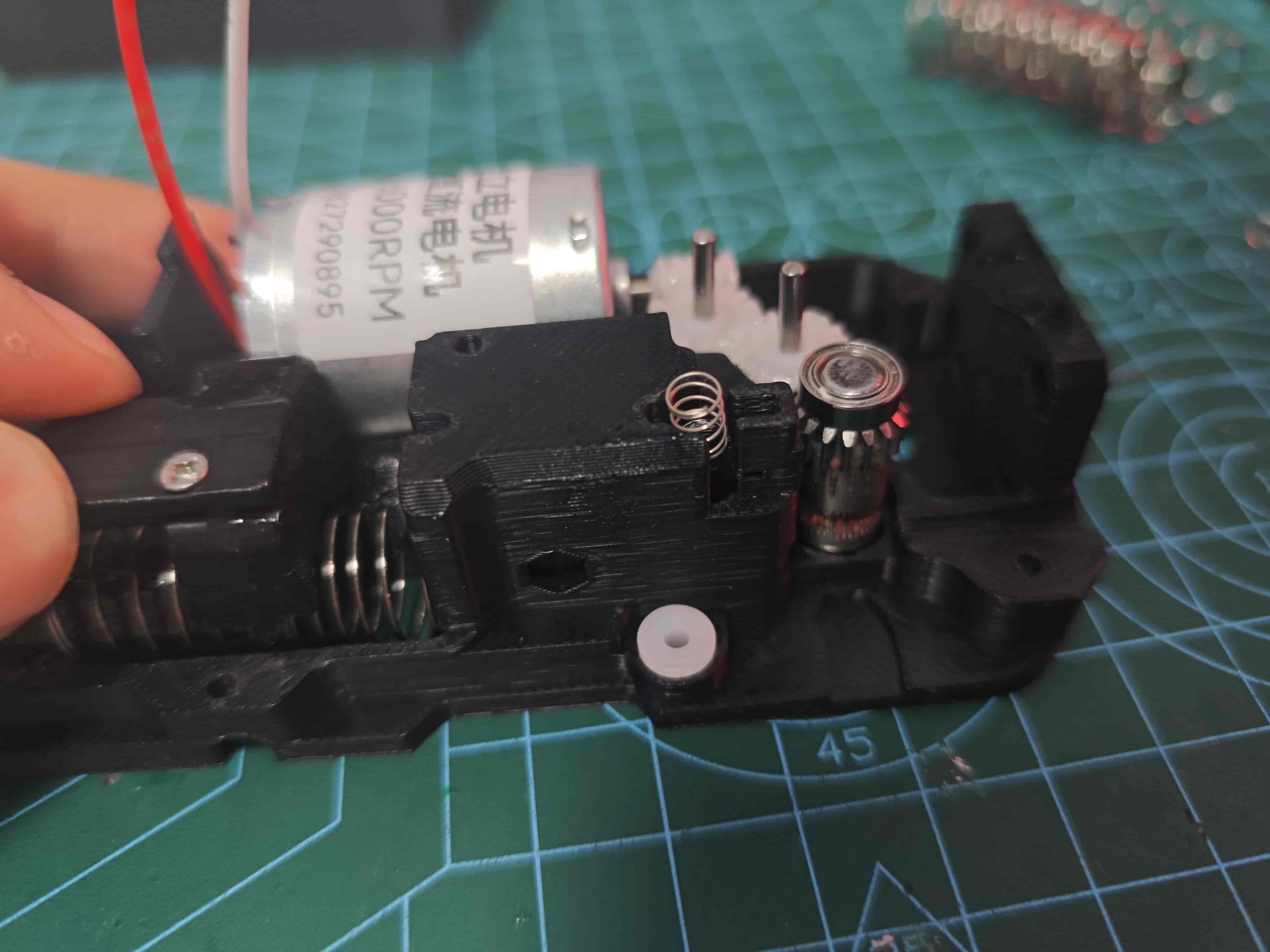
¶ Install Filament Break Slider Spring
Place one 0.3*4*5 spring above filament break slider
¶ Install Middle Frame
Attach middle frame to back cover, ensuring magnet portion of slider passes through
Secure with five M2*8 self-tapping screws
¶ Install Lever
If available, now we recommend 0.6415 springs, currently 10 lengths are considered too weak!
Place one 0.6*4*100.6*4*15 springin position, then install lever
Hold lever and insert D2*20 shaft
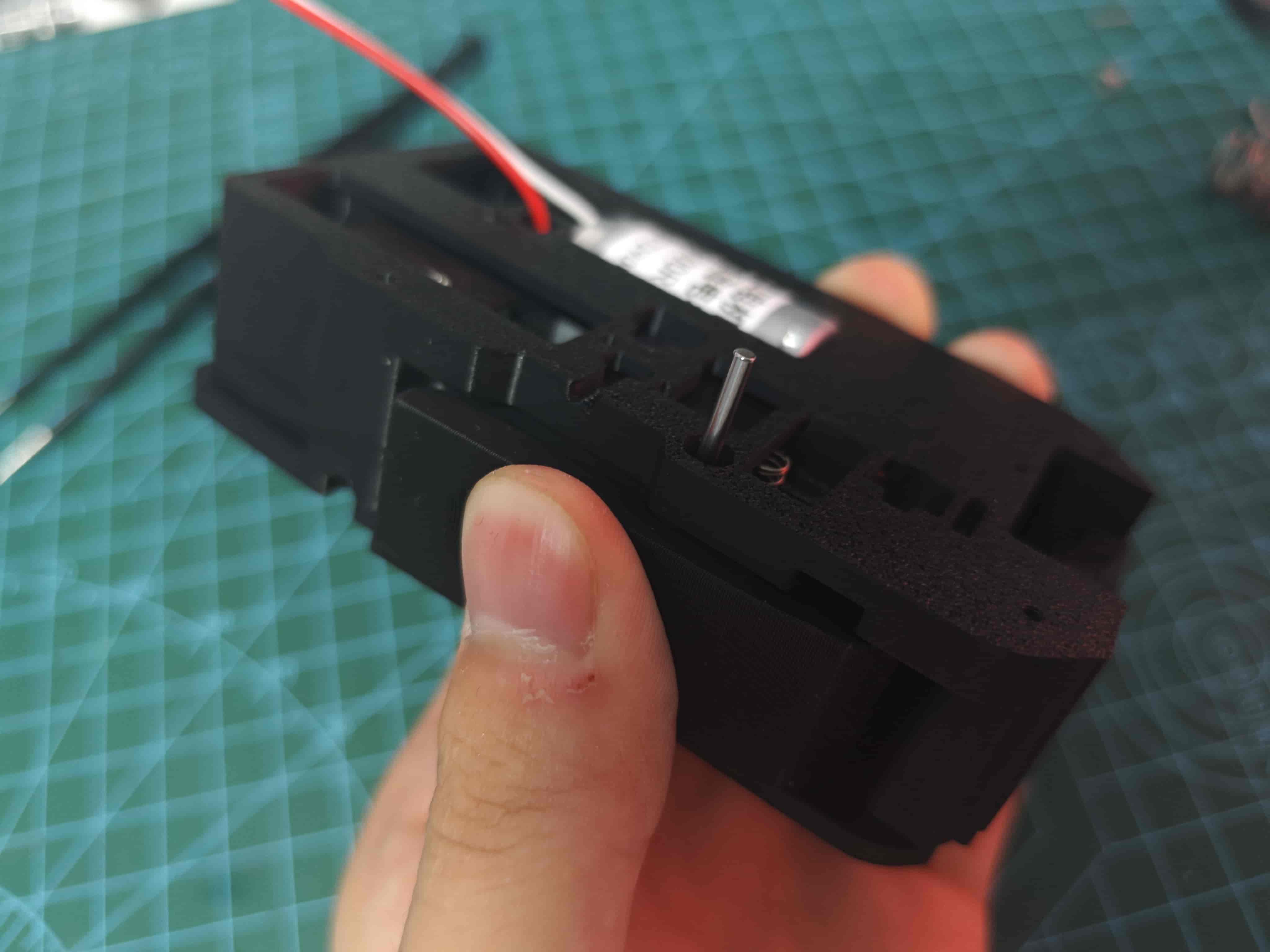
Press firmly to bottom, then use screwdriver to press into recess
¶ Install Radial Magnet
Attach D6*2.5 radial magnet above BMG drive wheel, ensuring it's not compressed and rotates with BMG (important)
At this point, insert filament and power motor with 12v~24v to
test filament feeding,verify magnet rotation, anddistribute lubricant
¶ Install Light Guider fiber
Insert 1.5mm fiber optic or simply a transparant PETG filament into small hole next to buffer slider, cut flush, for light guide
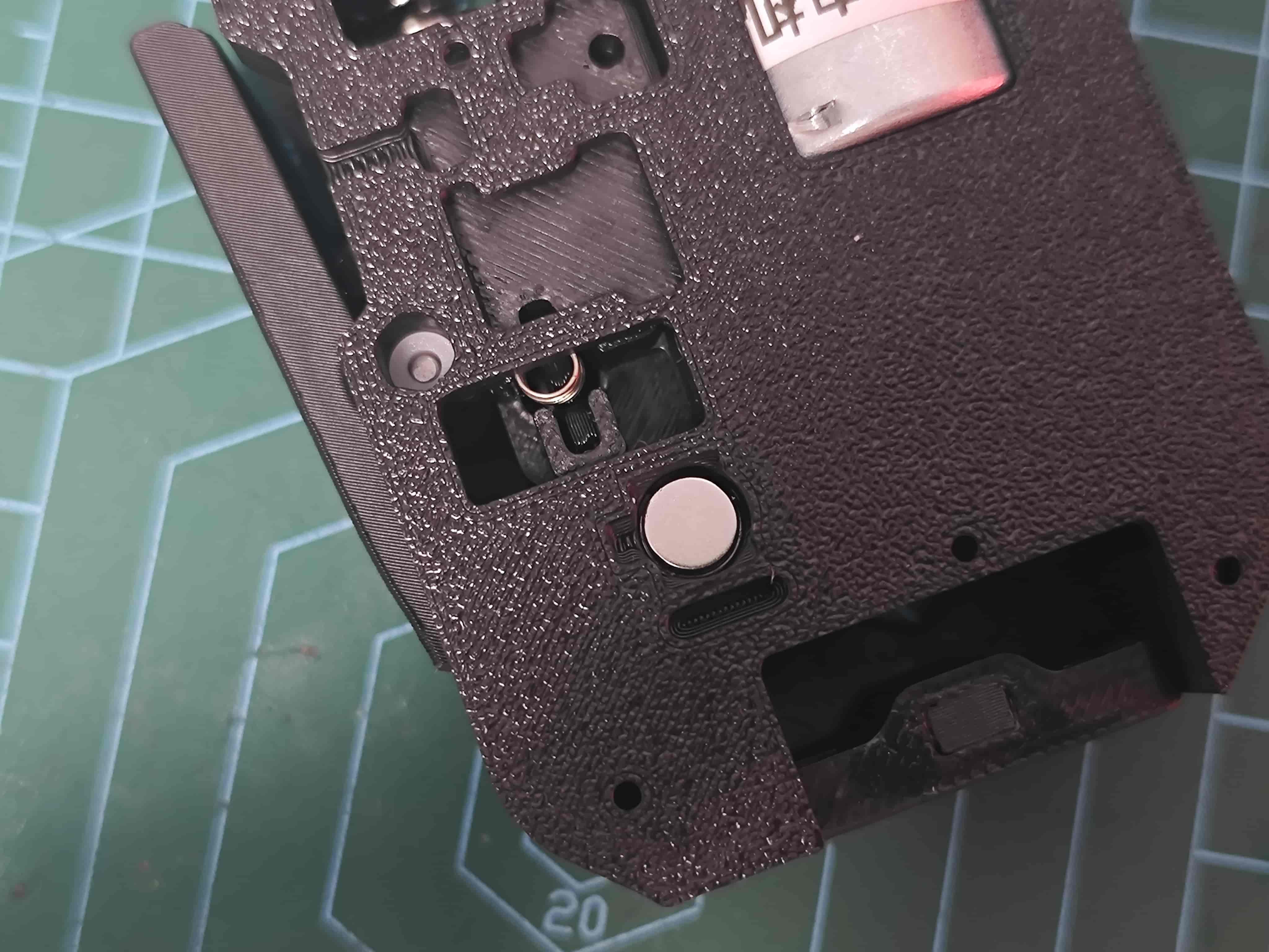
¶ Install Sub-board
Place sub-board in position
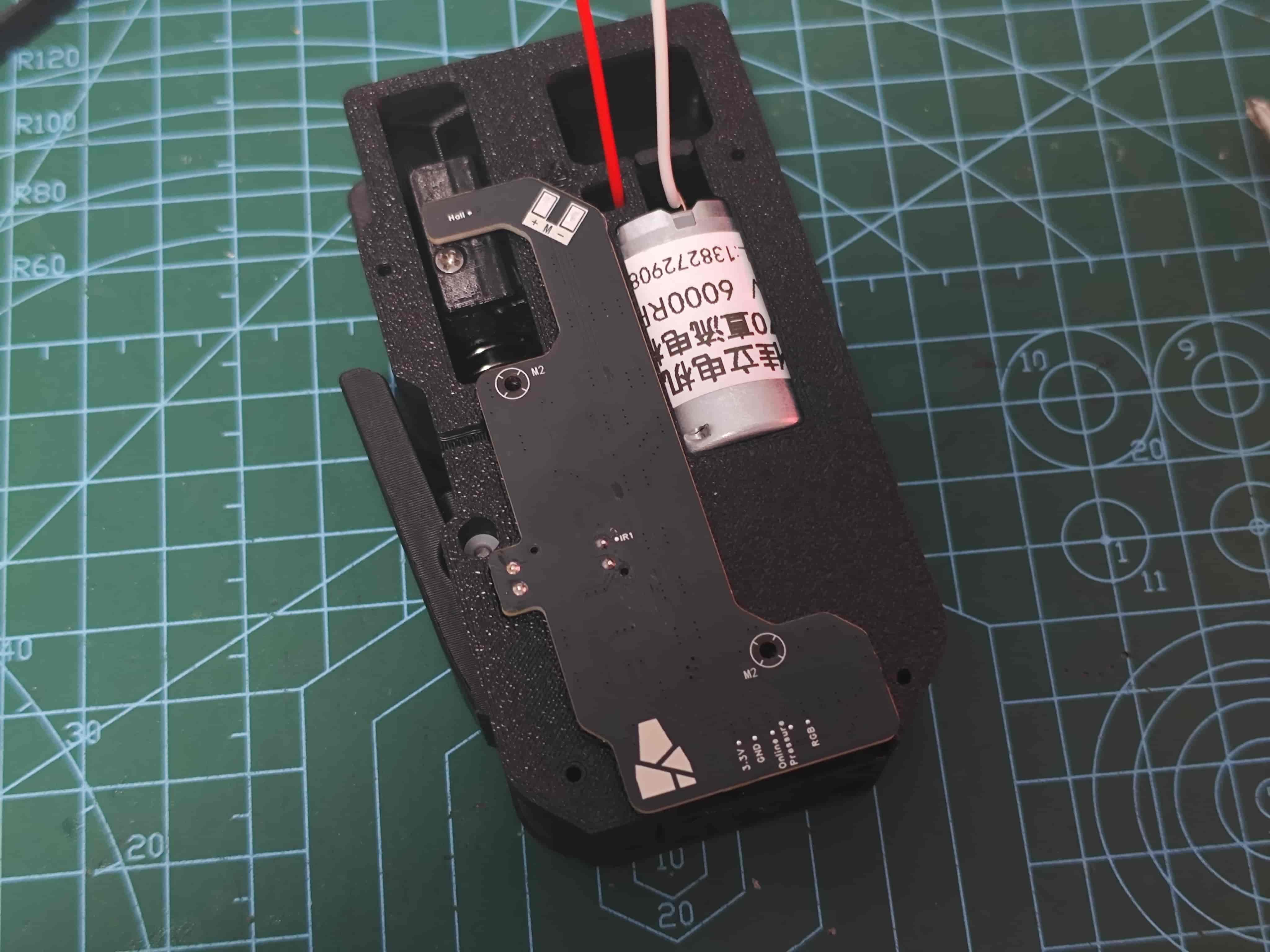
Secure with two M2*8 self-tapping screws and solder motor wires
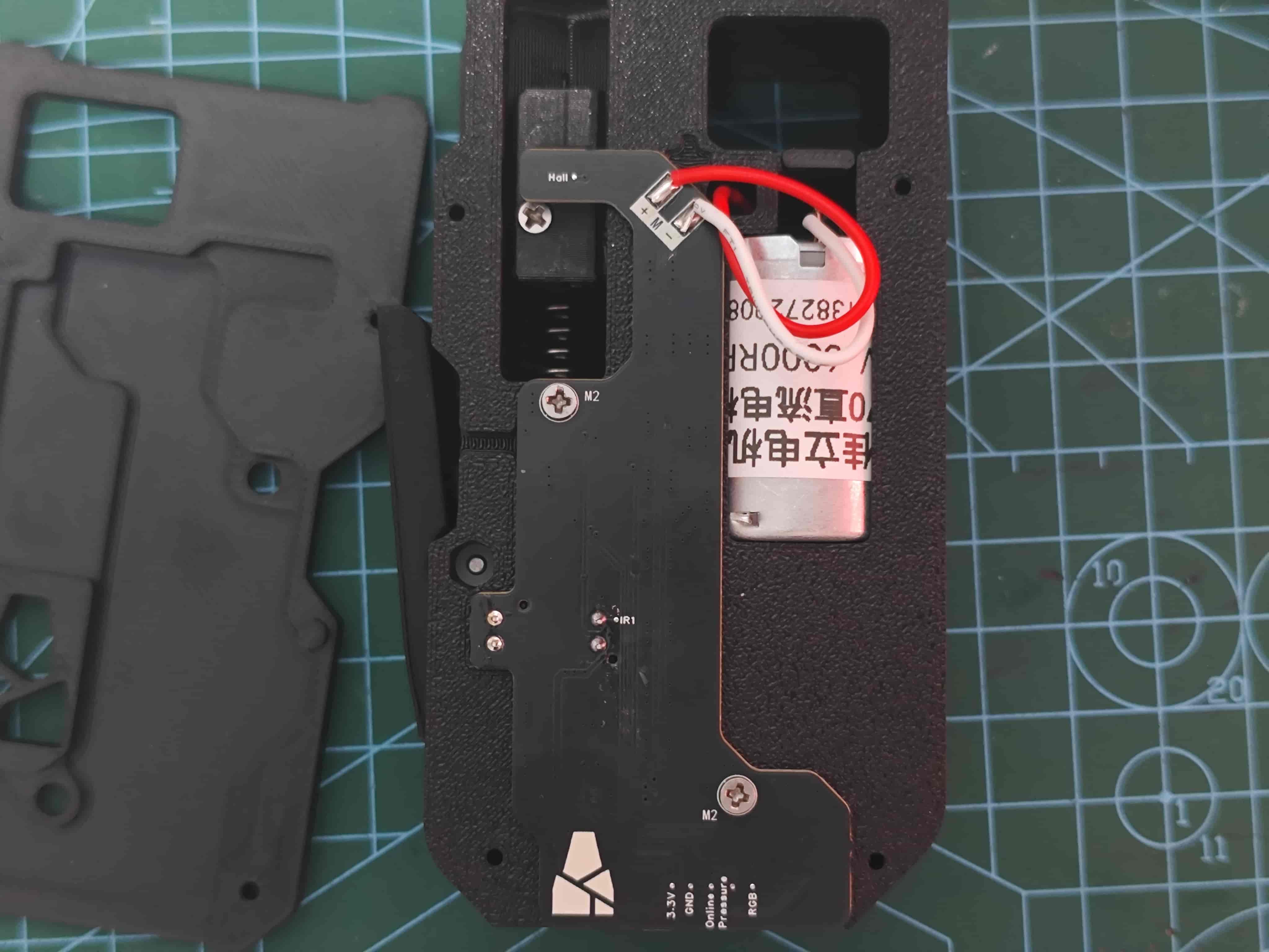
Tuck excess wires here
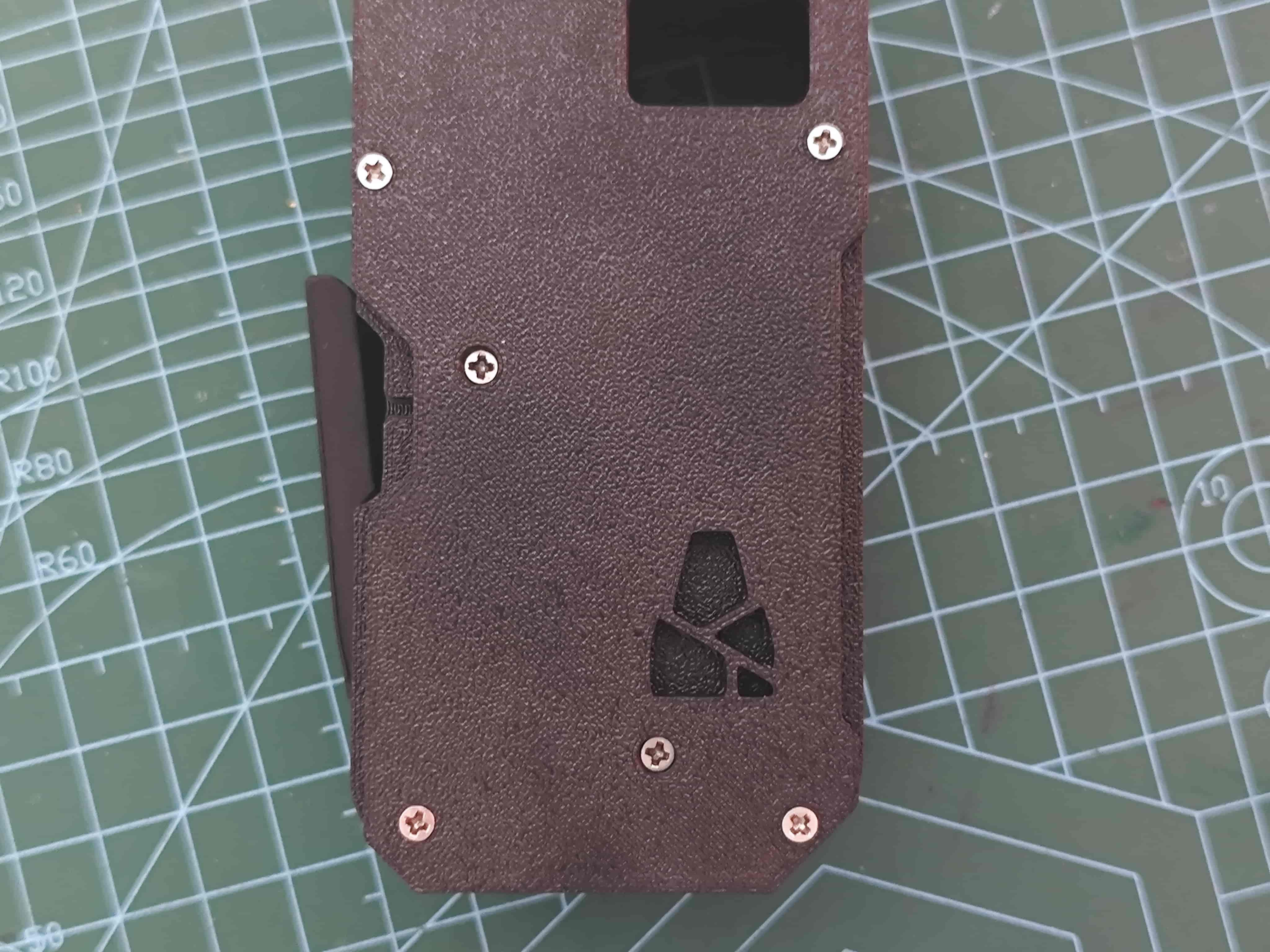
¶ Install Front Cover
Secure with four M2*8 self-tapping screws
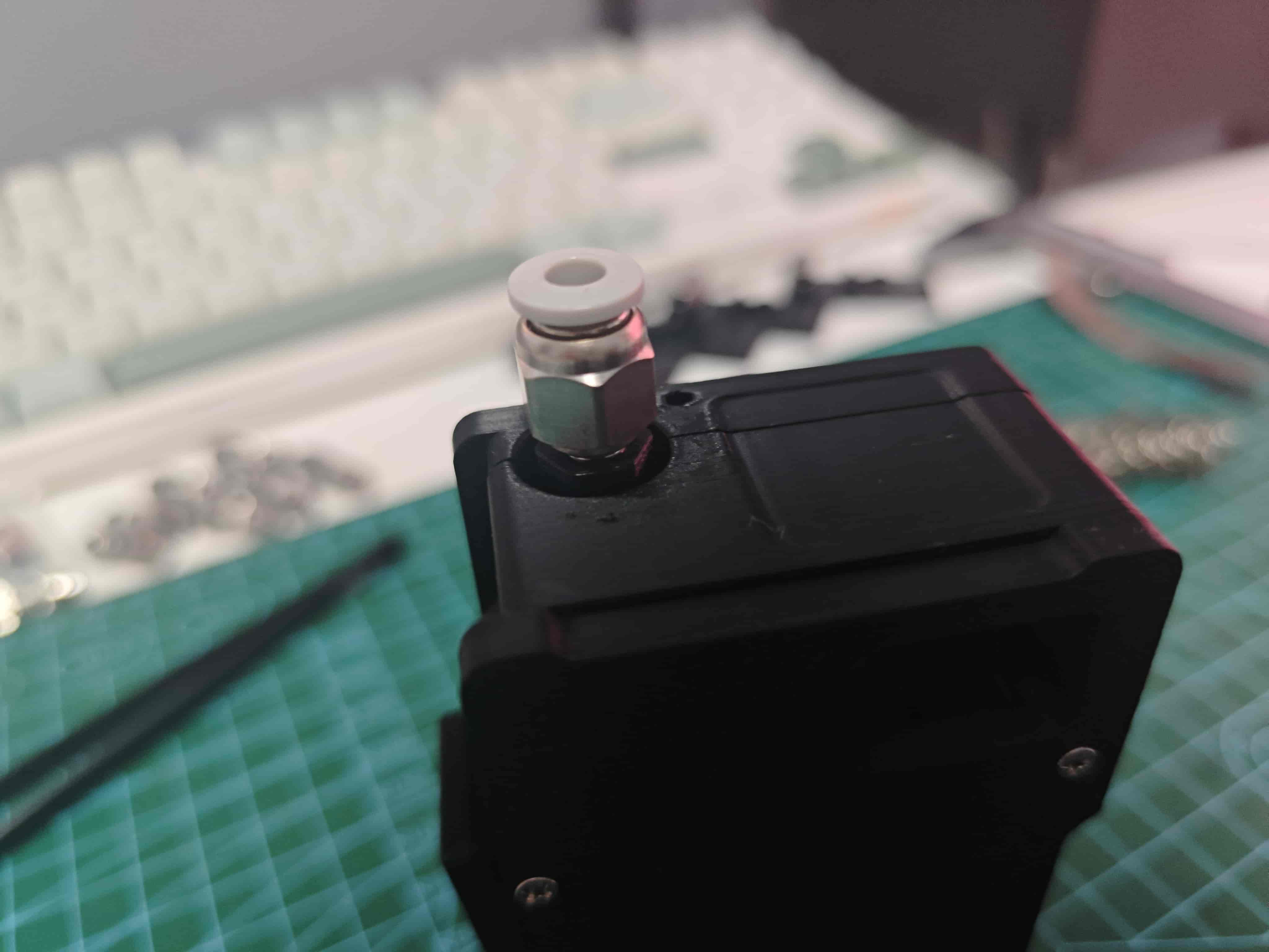
¶ Install Pneumatic Fitting
Screw pneumatic fitting onto slider
¶ LED Status
-in table indicates no effect on LED or unknown status
| Condition | Side LED | Top LED (Fiber) | Troubleshooting |
|---|---|---|---|
| No radial magnet | - | Red | Check radial magnet and AS5600 soldering |
| Normal operation | - | Blue | - |
| Channel selected (in use) | - | White | - |
| No filament | Black | - | - |
| Filament loaded | White | - | - |
| Buffer pressed (slider) | Blue | - | If red, reverse slider magnet |
| Buffer pulled out (slider) | Red | - | If LED blue, reverse slider magnet |
Mainboard: Blue for normal printer communication, red for abnormal, any other color indicates malfunction